General lnformation- 2215A Operators
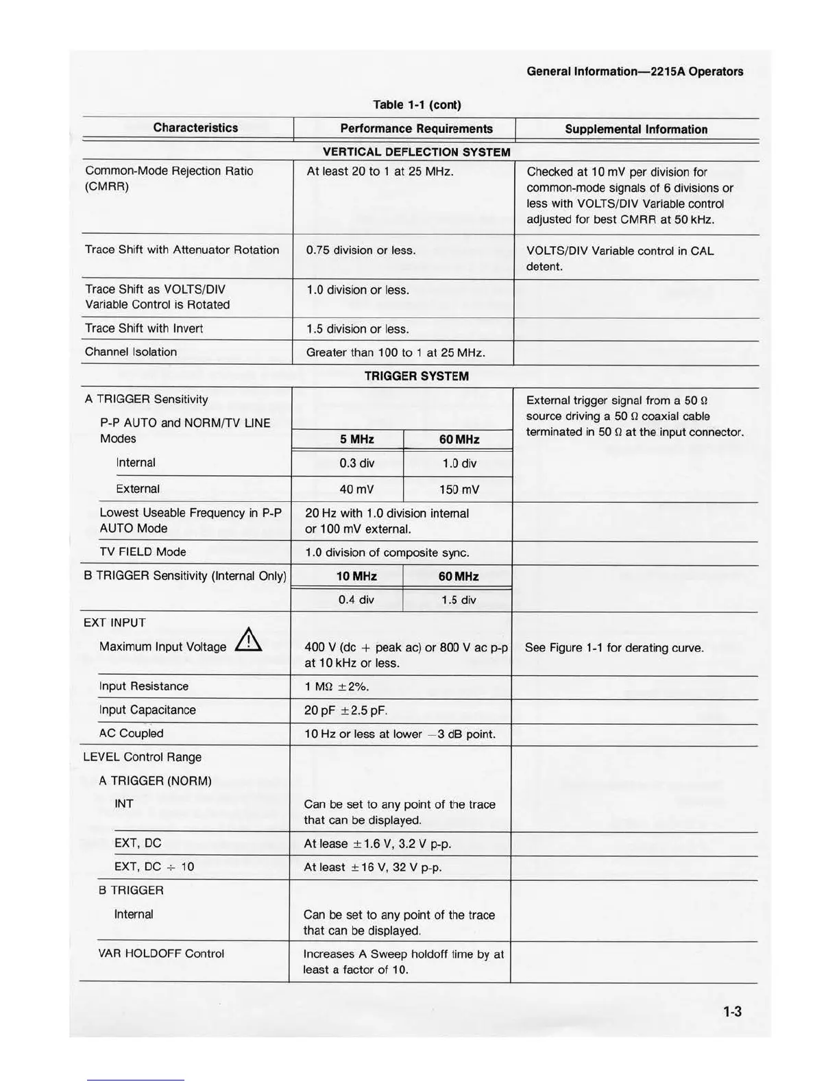
Table 1-1 (cont)
Characteristics
Performance Requirements
Suppleme
nt
al Information
VERTICAL DEFLECTION SYSTEM
Common-Mode Rejection Ratio
At
least
20
to
1
at
25
MHz.
Checked at
10
mV
per
division for
(CMRR)
common-mode signals
of
6 divisions
or
less with VO
LT
S/DIV Variable control
adjusted for best
CMRR
at
50 kHz.
Trace Shift with Attenuator
Ro
tati
on
0.75 division
or
less.
VOLTS/DIV Variable control in
CAL
detent.
Trace Shift
as
VOLTS/DIV
1 .0 division
or
less.
Variable Control is Rotated
Trace Shift with Invert
1
.5
division
or
less.
Channel Isolation
Greater than 100
to
1
at
25
MHz.
TRIGGER SYSTEM
A TRIGGER Sensitivity
External trigger signal from a 50
þÿ©
P-P AUTO and NORM/TV LINE
source driving a
50
þÿ©coaxial cable
Modes
5MHz
60MHz
terminated in
50
þÿ©
at
the
input connector.
Internal
0.3div
1.0
div
External
40mV
150 mV
Lowest Useable Frequency
in
P-P
20 Hz with 1.0 division internal
AUTO Mode
or
100
mV
external.
TV FIELD Mode
1.0 division
of
composite sync.
B TRIGGER Sensitivity (Internal Only)
10MHz
60MHz
0.4 div 1.5
div
EXT INP
UT
Maximum Input Voltage
400 V (de
+ peak ac)
or
800 V
ac
p-p
See Figure
1-1
for derating curve.
at
10
kHz
or
less.
Input Resistance 1
þÿM©
±2%.
Input Capacitance
20
pF
± 2.5 pF.
AC Coupled
10
Hz
or
less
at
lower - 3
dB
point.
LEVEL Control Range
A TRIGGER (NORM)
INT
Can
be
set
to
any point
of
the trace
that
can be displayed.
EXT, DC
At
lease ± 1.6 V, 3.2 V p-p.
EXT, DC
-;-
10
At
least ±
16
V,
32
V
p-p
.
B TRIGGER
Internal
Can
be
set
to
any point
of
the trace
that
can be displayed.
VAR HOLDOFF Control
Increases A Sweep holdoff time
by
at
least a factor
of
10.
1
-3

 Loading...


