Appendix C: Performance Verification
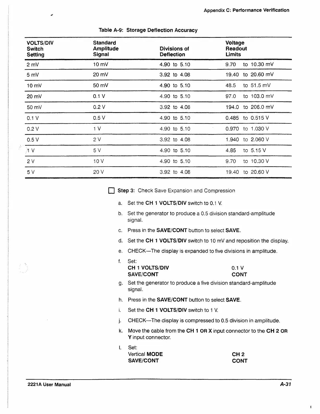
Table A-9: Storage Deflection Accuracy
VOLTS/DIV
Switch
Setting
Standard
Amplitude
Signal
Divisions of
Deflection
Voltage
Readout
Limits
2 mV
10 mV
4.90 to 5.10
9.70
to
10.30 mV
5 mV
20 mV
3.92 to 4.08
19.40
to
20.60 mV
10 mV
50 mV
4.90
to 5.10 48.5
to
51.5 mV
20 mV
0.1 V 4.90 to 5.10 97.0
to
103.0 mV
50 mV
0.2 V 3.92
to 4.08
194.0 to
206.0 mV
0.1 V
0.5 V
4.90
to 5.10
0.485 to
0.515 V
0.2 V
1 V
4.90
to 5,10
0.970 to 1.030 V
0.5 V
2 V
3.92
to 4.08
1.940 to 2.060 V
1 V
5 V
4.90
to 5.10
4.85
to 5.15 V
2 V
10 V
4.90
to
5.10
9.70 to
10.30 V
5 V
20 V
3.92 to
4.08
19.40
to
20.60 V
□ SteP 3: Check Save Expansion and Compression
a. Set the CH 1 VOLTS/DiV switch to 0.1 V.
b. Set the generator to produce a 0.5 division standard-amplitude
signal.
c. Press in the SAVE/CONT button to select SAVE.
d. Set the CH 1 VOLTS/DIV switch to 10 mV and reposition the display.
e. CHECK^The display is expanded to five divisions in amplitude.
f. Set;
CH 1 VOLTS/DIV 0.1 V
SAVE/CONT CONT
g. Set the generator to produce a five division standard-amplitude
signal.
h. Press in the SAVE/CONT button to select SAVE.
i. Set the CH 1 VOLTS/DIV switch to 1 V.
j. CHECK—The display is compressed to 0.5 division in amplitude.
k. Move the cable from the CH 1 OR X input connector to the CH 2 OR
Y input connector.
l. Set:
Vertical MODE CH 2
SAVE/CONT CONT
2221A User Manual
A-37

 Loading...


