Checking the Probe Compensation
NOTE
Always compensate a probe for the particular channel that you use
it with.
Use the following procedure to check the probe compensation:
Step 1: Set the instrument controls as described in Setting up the
Display.
n §tep 2: Connect the probe to the channel you intend to use it for.
{If the probe is properly “coded” the volts-per-division readout for the chan
nel will change to match the attenuation factor of the probe. The 10X probes
supplied with the oscilloscope already have the proper coding.)
□ SteP 3: Clip the probe tip to the PRB ADd connector.
f~| Step 4: Use the VOLTS/DIV control to display about 5 divisions of the
waveform,
□ Step 5: Use the VERTICAL POSITION and HORIZONTAL POSITION
controls to center the display.
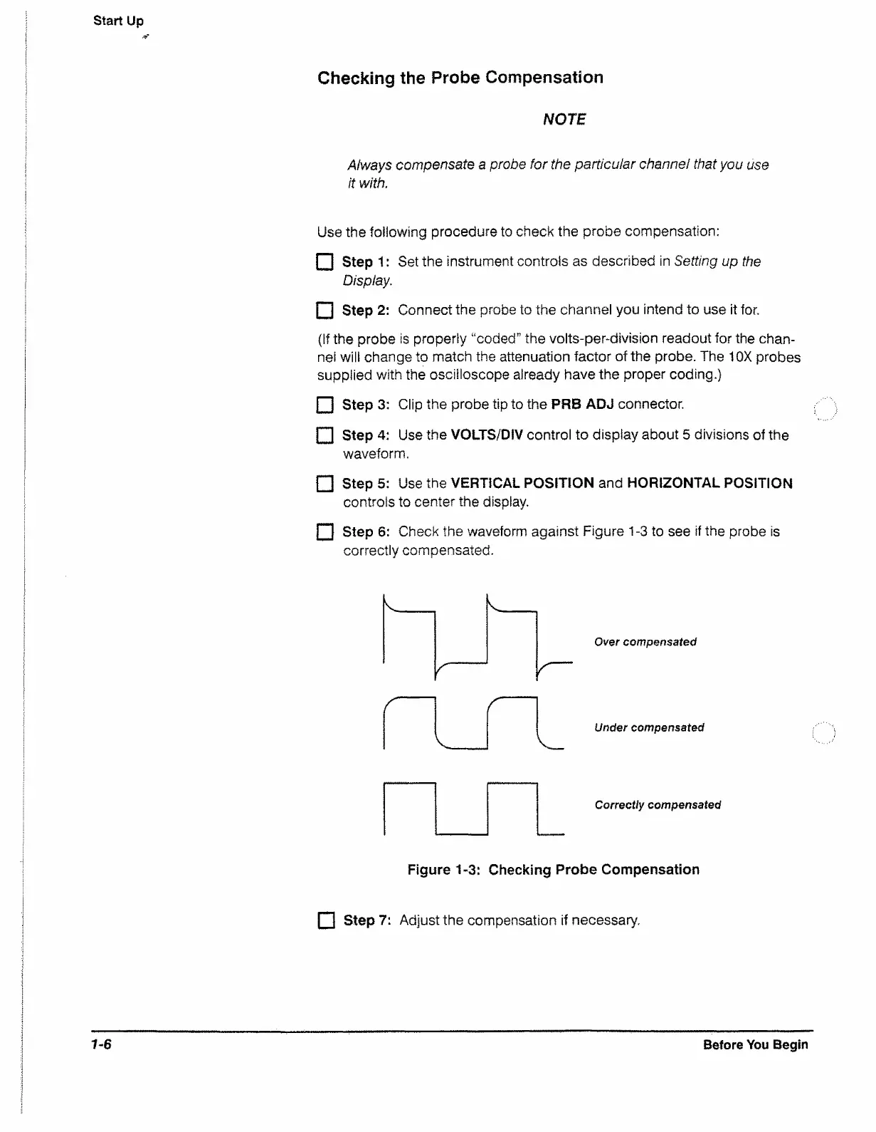
F I Step 6: Check the waveform against Figure 1-3 to see if the probe is
correctly compensated.
r
Over compensated
r
r
v .
Under compensated
Correctly compensated
Figure 1-3: Checking Probe Compensation
f~l Step 7: Adjust the compensation if necessary.
7-6
Before You Begin

 Loading...


