Measuring signals
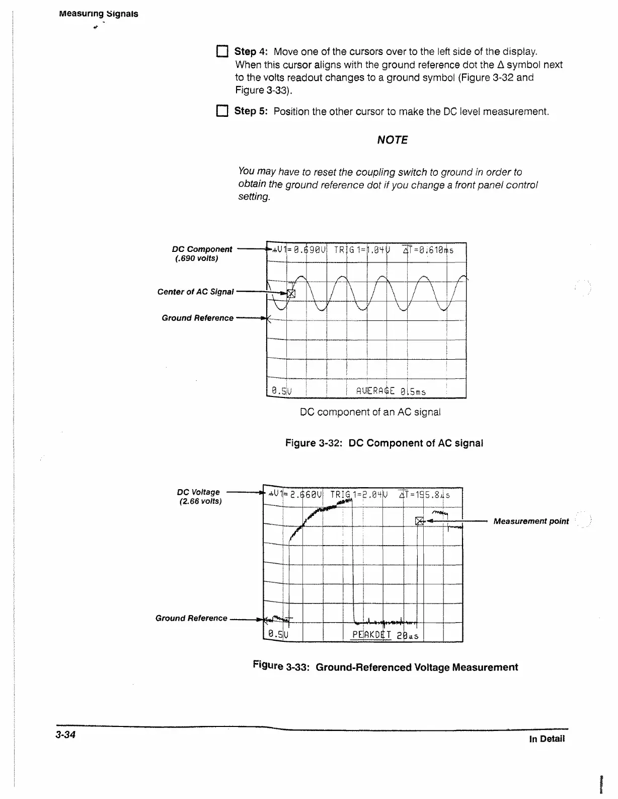
□ Step 4: Move one of the cursors over to the left side of the display.
When this cursor aligns with the ground reference dot the A symbol next
to the volts readout changes to a ground symbol (Figure 3-32 and
Figure 3-33),
□ Step 5: Position the other cursor to make the DC level measurement.
NOTE
You may have to reset the coupling switch to ground in order to
obtain the ground reference dot if you change a front panel control
setting.
DC Component
(.690 volts)
Center of AC Signal
Ground Reference
Figure 3-32: DC Component of AC signal
Measurement point
figure 3-33: Ground-Referenced Voltage Measurement
3-34
In Detail

 Loading...


