Displaying Signals
Limiting Bandwidth
BW LIMIT
Modulating the
Display intensity
High-frequency noise from extraneous sources can sometimes interfere with
a signal display. Push in the BW LIMIT button on the front panel to limit the
vertical response of the scope to frequencies below 20 MHz. A “BWL” read
out will also appear on the display.
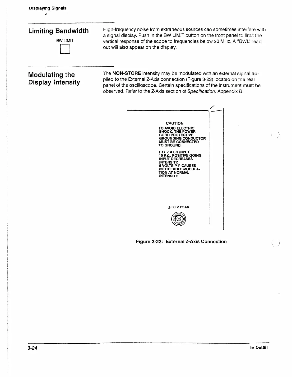
The NON-STORE intensity may be modulated with an external signal ap
plied to the External Z-Axis connection (Figure 3-23) located on the rear
panel of the oscilloscope. Certain specifications of the instrument must be
observed. Refer to the Z-Axis section of Specification, Appendix B.
CAUTION
TO AVOID ELECTRIC
SHOCK. THE POWER
CORD PROTECTIVE
GROUNDING CONDUCTOR
MUST BE CONNECTED
TO GROUND.
EXT Z AXIS INPUT
10 KA. POSITIVE GOING
INPUT DECREASES
INTENSITY
5 VOLTS P-P CAUSES
NOTICEABLE MODULA
TION AT NORMAL
INTENSITY.
< 30 V PEAK
Figure 3-23: External Z-Axis Connection
3-24
In Detail

 Loading...


