EasyManuals Logo
Home>Tektronix>Test Equipment>2235

Tektronix 2235 User Manual

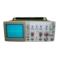
Tektronix 2235
229 pages
To Next Page IconTo Next Page
To Previous Page IconTo Previous Page
Page #104 background imageLoading...
Page #104 background image
1
.
R
emove
t
he
P
ower-Su
pp
ly
sh
ield
(see
t
h
e
"
P
owe
r -
Sup
p
ly
S
h
iel
d
"
removal
p
r
oce
du
re)
.
2
.
R
emove
t
he
five
wires
to
t
he F
ilte
r
circ
u
it
boar
dby
unsoldering
two
wires
from
t
h
e
M
ain
circ
u
it
b
oard,
two
fr
om
t
he
li
n
e
filter,
and
one
wire
from
t
he
f
u
se
h
olde
r
(pull
the
protective
cap
com
p
letely
off
t
he
f
use
h
older
b
efore
un
solderi
n
g)
.
3
.
R
emove
two
screws
securi
n
g
t
he F
ilter
ci
r
cuit
b
oa
r
d
to
t
he
bac
k
of
t
he ch
assis
frame
.
L
ift
t
he F
ilter
ci
r
cuit
b
oard
out
of
t
h
e
instrument
.
To
reinstall
t
he F
ilter
circ
u
it
b
oard
,
p
erform
t
h
e
following
ste
p
s
.
4
.
R
einstall
two
screws
securing
t
he
F
ilter
circ
u
it
board
to
t
he
b
ac
k
of
t
he
c
h
assis
frame
(removed
in
ste
p
3)
.
5
.
R
esol
d
er
t
h
e
five
wires
f r
om
t
he F
ilter
circ
u
it
b
oa
r
d
to
t
h
e
M
ain
circuit
b
oard,
line
filter,
an
d
fuse
h
ol
d
er (unsol
d
ered
i
n
ste
p
2)
.
6
.
R
ei
n
stall
t
he
P
ower-Su
p
ply
sh
ield
(see
t
he
"
P
ower-
Supply
S
h
ield"
reinstallatio
n procedu
re)
.
Alt
Swee
p
Circ
u
it
B
oard
To
remove
t
h
e
Alt
Sweep
circ
u
it
boar
d
,
p
erform
t
he
fol-
lowing
steps
:
4
.
R
einstall
t
he
Alt
Swee
p
circuit
b
oard
into
t
he
p
lastic
h
older attac
h
ed
to
t
he
P
ower-Sup
p
ly
sh
ield
.
Atte
n
uato
r
Circ
u
it
B
oa
rd
M
ai
ntenan
ce-2235
Service
To
remove
t
h
e
Attenuator
circuit
b
oard,
p
erform
t
he
fol-
lowing ste
ps
:
1
.
U
se α
1/16-i
nch
H
ex-
k
ey
wrenc
h
to
loosen
t
he
set
screws
on
bot
h
t
h
e
C
H
1
and
t
he
C
H
2
VO
LTS/DI
V
V
ariable
k
nobs
and
remove
t
h
e
knobs
.
2
.
Set
t
he
C
H
1
and
t
he
C
H
2
V
O
L
TS/DI
V
switc
h
es
to
t
he
same
p
osition
.
N
ote
switc
h
positio
n
s
for
rei
n
stallatio
n
reference
;
t
hen
remove
t
h
e
k
nobs
b
y
pulli
ng
t
h
em
st
r
aig
h
t
out from
t
he
fro
n
t
p
anel
.
3
.
P
lace
t
h
e
instrument
on
its
si
de
an
d
remove
two
screws
securing
t
he
Atten
u
ato
r
board
to
t
h
e
subpan
el (lo-
cated
u
nder
n
eat
h
t
h
e
C
H
1
and
C
H
2
i
npu
t
con
n
ectors)
.
4
.
U
nsol
d
er
t
h
e
r
esisto
r
s from
t
he
C
H
1
and
C
H
2
i
npu
t
connectors
.
5
.
R
emove
t
he
followi
n
g
co
nn
ectors
from
t
he
Atten
uato
r
circ
u
it
board, noting
t
h
eir
locatio
ns
for
r
einstallation
refere
nce
:
α
.
Ρ
9103, α
four-wire
connector
located
beh
i
n
d
t
he
C
H
1
V
O
LTS/DI
V
switc
h
assem
b
ly
.
b
.
Ρ
9108,
α
four-wire
con
nector
located
beh
ind
t
he
C
H
2
V
O
L
TS/DI
V
switc
h
assem
b
ly
.
c
.
Ρ
9091,
α
t
h
ree-wi
r
e
connector
located
b
etween
t
he
C
h
annel
1
a
nd
C
h
an
n
el
2V
ariable
p
ote
n
tiometers
at
t
h
e
rear
of
t
he
Atten
u
ator
circuit
boar
d
.
1
.
U
se α vacu
u
m-desolderi
ng
tool
to
unsolder
t
h
e
27
p
i
n
s
(between
t
h
e
Alt
Swee
p
ci
r
cuit
board
and
t
he
M
ain
cir
cuit
board)
from
t
he
M
ai
n
ci
r
cuit
boar
d
.
6
.
R
emove
four
screws
securing
t
he
Top
s
h
iel
d
to
b
ot
h
t
h
e
Attenuator
circuit
b
oa
r
d
and
t
h
e
b
ottom
sh
iel
d
.
2
.
R
emove
t
h
e
Alt
Sweep
circuit
boar
d
fr
om
t
he
i
n
st
r
u-
ment
b
y
u
nclippi
ng
it
from
t
h
e
plastic h
older attac
h
ed
to
t
he
7
.
R
emove
two
screws
and
t
h
e
groun
d
stra
p
from
t
h
e
P
ower-Sup
p
ly
s
h
ield
.
rear
of
t
h
e
Atten
u
ator
circuit
board
.
To
rei
n
stall
t
he
Alt
Sweep
circ
u
it
b
oard,
p
erform
t
he
fol-
8
.
Pull
t
h
e
Atte
nu
ator
board
straig
h
t
bac
k
f
r
om
t
he
front
lowing
steps
:
of
t
he
i
n
strument
un
til
t
he
circ
u
it
board
interco
nn
ecting
p
i
ns
3
.
Insert
t
h
e
27
p
i
ns
of
t
he
Alt
Sweep
circ
u
it
b
oard
into
are
disengage
d
and
t
he
switc
h sh
afts
a
r
e
clear
of
b
ot
h
t
h
e
Fr
ont-
P
anel
circuit
boa
rd
and
t
he
two
AC-G
N
D-DC
switc
h
t
he
M
ai
n
ci
r
cuit
board
.
s
h
afts
(located
b
etwee
n
t
he
fro
n
t-
pan
el
and
t
he su
b
panel
.
To
reinstall
t
h
e
Attenuator
circuit
b
oard,
p
erform
t
he
fol-
lowing
ste
p
s
:
9
.
Insert
t
h
e
two
V
O
LTS/DI
V
switc
h
s
h
afts
and
t
he
AC-
5
.
R
esol
d
er
t
he
27
p
ins
to
t
he
M
ain
circuit
board
(
u
nsol-
G
N
D-DC
switc
h
s
h
afts
into
t
he
front
panel
h
oles
.
E
nsu
re
d
ered
i
n
step
1)
.
t
h
at
t
h
e
interconnecti
ng
p
i
n
s
are
aligned
wit
h
t
he
Front-Pan-
6-
1
5

Table of Contents

Other manuals for Tektronix 2235

Questions and Answers:

Question and Answer IconNeed help?

Do you have a question about the Tektronix 2235 and is the answer not in the manual?

Tektronix 2235 Specifications

General IconGeneral
BrandTektronix
Model2235
CategoryTest Equipment
LanguageEnglish

Related product manuals