EasyManuals Logo
Home>Tektronix>Test Equipment>2235

Tektronix 2235 User Manual

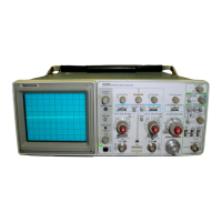
Tektronix 2235
229 pages
To Next Page IconTo Next Page
To Previous Page IconTo Previous Page
Page #38 background imageLoading...
Page #38 background image
T
h
eo
ry of
O
p
eratio
n
-2235
Service
T
he outp
ut
stage
of
the
Am
p
lifier
utilizes
two
totem-pole
line
.
The
Α&Β
ΙΝΤ
switch
selects
either
Channel
1
or
Chan-
transistor
p
airs,
0254-Q256
and
0255-Q257,
that
convert
nel
2 as
the
trigger
source,
and
the
Α
SOURCE
switch
se
the
collector
currents of
Q230
and
Q231
to
p
roportional
out-
lects
between
internal,
line,
or external
trigger
sources
.
put
voltages
.
R
esistors
R
256,
R
258,
R
257,
and
R
259
serve
as
fee
d
back
elements
and
also as
divider
networks so
that
each
transistor
in
α
p
air
dro
p
s
h
alf
the
final
out
p
ut
voltage
.
Internal
Trigger
T
he
Am
p
lifier
out
p
ut
signals
are app
lied
to
the
vertical
de-
flection
p
lates
of
the
crt
to
p
roduce
deflection
of
the
crt
Signals
from
the
V
ertical
P
reamplifiers
drive
the
Internal
beam
.
Trigger
Amplifier
with
c
hannel
selection
determined by
the
VERTICAL
and
H
ORIZONTAL
MODE
switches
.
BW
LIMIT
switch
S226,
C228
and
C229,
and
α
diode
b
ridge consisting
of
CR226,CR227,CR228,
and
CR229,
Trigger
p
ickoff
from the
Preamplifiers
is
accom
p
lished
by
are
utilized
to
reduce
the
bandwidth
of
the
Am
p
lifier
if
de-
Q302
and
Q303
for
Channel
1,
and
0327
and
Q328
for
sired
.
W
ith
t
he
b
andwidth
limit
off,
R
226
is
grounded
and
Channel
2
.
The
circuitry
associated
with
C
hannel
2
is
the
the
n
onconducting
diode
bridge
isolates
C228
and
C229
.
same
as
that
for
Channel
1
except
that
it
does
not
h
ave
α
W
ith
bandwidth
limit
on,
R
226
is
connected
to
the
+8
.6
V
trigger
offset
adjustment
.
supply
and
t
he
d
iode
bridge
conducts
.
The
two
capacitors
are
no
longer
isolated
a
nd
will
attenuate
h
igh-frequency
signals
.
Signals
from
the
Channel
1
P
reamplifier
a
re
applied
to
0302
and
Q303
.
These
emitter-follower
transistors
each
drive
one
input
transistor
in
U310,
and
t
he
collectors
of
the
BEAM
F
IND
switch
S390
adjusts
output-amplifier
bias-
U310
input
transistors
in
turn
supply
emitter current
to
two
ing
to
limit
the
voltage
swing
at
the
crt
plates
.
This
k
eeps
current-steering
transistors
.
The
compensation
and
biasing
the
vertical
trace
within
the
graticule
area
for
locating
off-
network
connected
to
the
emitters
of
the
input
transistors
in
screen
traces
.
W
ith
t
he
switch
in
the normal out p
osition,
U
310
is
fixed
for
C
hannel
2
but
not
for
C
hannel
1
.
P
otenti-
the
-8
.6
V
sup
p
ly
provides
emitter current
to
the
Amplifier
ometer
R309
ad
justs
the
emitter
bias
levels
of
the
two
input
output
stagethrough
R261
.
When
the
BEAM
F
IND
switch
is
transistors
so
that
do
offsets
b
etween
c
hannels
can
be
in,
the
d
irect
-8
.6
V
supply
to
R
261
is
removed
and
emitter
matched
.
current
is
now
supplied
through
R261
and
R262
in
series
.
This
reduces
the
amount
of
available
emitter
current
and
The
b
ase b
ias
voltages
of
one
transistor
in
each
o
utput
limits
the
Amplifier
dynamic
r
ange
.
differential
amplifier
p
air
is
fixed
by
the
divider
network
com-
posed
of
R
321
and
R
322
.
The
other
base
voltage
is
εοη
Α
/
Β
Sweep
Separation
Circuit
trolled
by
the
Ch
1
Trig
li
ne from
the
Trigger
C
hannel
Switch
.
When
t
he
Ch
1
Trig
signal
is
HI,
the
transistors
in
The
circuit
composed
of
Q283,
Q284,
Q285,
and
associ-
each
output
p
air
with
t
he
collectors
connected
together
are
ated
components
p
rovides
α
means
of
vertically
positioning
b
iased
on
and
the
other
transistors
are
off
.
The
collector
the
Β
trace
with
respect
to
the
Α
trace
during
Alt
H
orizontal
signal
currents
are
e
q
ual
in
magnitude
bu
t
opposite
i
n
polari-
Mode
displays
.
During
the
Β
Sweep
i
nterval,
the
Se
p
signal
ty
and
signal
cancellation
occurs
.
If
the
Ch
1
Trig
signal
is
from
the
Alternate
Dis
p
lay
Switching
circuit
is
L
O
and
Q283
LO,
the
other
transistors
in
each
pair
will
be
biased
on
and
is
b
iased
off
.
This
allows
Α
/
Β
SWP
S
EP
potentiometer
an
output
signal
will
b
e
developed
across
R
314
and
R
315
to
R
280
to
affect
the b
ias
on
one
side of
α
differential
current
drive
the
Internal
Trigger
Amplifier
.
source
com
p
osed
of
Q284
and
Q285
.
This supplies
α do
offset
current
to
the
V
ertical
Output
Amplifier
and
c
hanges
the
p
osition
of
the
Β
trace
on
the
crt
screen
.
Internal
trigger
channels
are
chosen
by
the
Α
&
Β
ΙΝΤ
switch
with
t
he
Α
SOURCE
switch
set
to
INT
.
T
he ΙΝΤ
p
osi-
tion
of
S392
reverse
b
iases
CR393
and
C
R399
to
p
revent
During the
Α
Swee
p
i
nterval,
the
Sep
signal
is
HI
and
external
trigger
signals
or
the
line
trigger
signal
from
reach-
Q283
is
turned
on
.
The
b
ase
voltages
of
Q284
and
Q285
ing
the
Α
Trigger
Generator
.
Signals
from the
Internal
Trig-
are
then
the
same,
and
equal
current
is
supplied to
both
ger
Am
p
lifier
are
p
assed
to
the
Α
Trigger
Generator
t
hrough
si
des
of
the
V
ertical
Output
Amplifier
so
that
no
offset
of
the
forward-biased
CR372
.
Α
t
race
occurs
.
C
HANNEL
1
.
F
or
triggering
from
Channel
1,
the
Α
&
Β
ΙΝΤ
switch
is
set
to
CH
1
.
The
ΧΥ
line
connected
to
S555
will
be
TR
IGG
ER
A
MPL
I
F
I
ER
S
A
N
DS
W
ITC
H
I
N
G
at
ground
potential
and
one
in
p
ut
of
U555B
will
be
held
LO
by
CR556
.
The
output
of
U
555B
will
then
also
be
L
O
and
The
Trigger
Am
p
lifiers,
shown
on
Diagram
3,
provide
sig-
the
Channel
1
signal
path
t
hrough
U310
will
be
enabled
.
The
nals
to
the
Α
Trigger
Generator
circuit
from
either
the
V
erti-
Channel
2
signal
p
ath
is
d
isabled
by
the
outputs
of
both
cal
P
reamplifiers,
the
ΕΧΤ
INPUT
connector,
or
the
p
ower
U
555C
and
U565B
being
HI
.
3-
7

Table of Contents

Other manuals for Tektronix 2235

Questions and Answers:

Question and Answer IconNeed help?

Do you have a question about the Tektronix 2235 and is the answer not in the manual?

Tektronix 2235 Specifications

General IconGeneral
BrandTektronix
Model2235
CategoryTest Equipment
LanguageEnglish

Related product manuals