EasyManuals Logo
Home>Tektronix>Test Equipment>2235

Tektronix 2235 User Manual

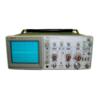
Tektronix 2235
229 pages
To Next Page IconTo Next Page
To Previous Page IconTo Previous Page
Page #11 background imageLoading...
Page #11 background image
Sp
ecification-2235
Service
Deflection
F
acto
r
R
ange
Accuracy
+15°C
to
+35°C
0°C
to
+50°C
Step
R
es
p
onse
R
ise
Time
Aberratio
ns
Ch
a
r
acteristics
2
m
V
p
er
Division
2
m
V
per
Divisio
n
P
ositive-Going
Ste
p
2
m
Vp
er
Division
to
0
.5
V
per
Division
1
V
pe
r
Division
to
5Vp
er
Division
Band
widt
h
(-3
dB
)
0°C
to
+35°C
5
m
V
per
Division
to
5
V
per
Division
2
m
V
per
Divisio
n
+35°C
to
+50°C
5
m
V
pe
r
Division
to
5
V
per
Division
.
2
m
V
p
er
Division
AC
Co
u
pled
L
ower
L
imit
VER
TICA
L
DEFLE
CTIO
N
SYST
EM
2
m
V
p
er
divisio
n
to
5Vp
er
d
ivisio
n
i
n α
1-2-5
se
q
uence
+2%
.
±3
ο
/
ο
.
α
R
ange
of
V
O
L
TS/DI
VV
aria
b
le
Cont
r
ol
Continuously
varia
b
le
b
etween
settings
. I
ncreases d
eflection
factor
by
at
least
2
.5
to
1
.
0°C
to
+35°C
5
mV
p
er
Division
to
5
V
per
3
.5
n
s
or
less
.'
Division
3
.9
ns
or
less
.a
+35°C
to
+50°C
5
m
V
p
er
Division
to
5
V
per
3
.9
n
s
or
less
.'
Division
4
.4
ns or
less
.a
+4
ο/ο
,
-4%,4%
ρ
-
ρ
.
+12%,
-12
ο
/
ο
,
12
ο
/
ο
ρ
-
ρ
.
α
Dc
to at
least
100
MH
z
.
Dc
to
at
least
90
MH
z
.
Dc
to at
least
90
MHz
.'
Dc
to at
least
80
MHz
.'
10
H
z
or
less
at
-3
d
B
.a
'
P
erfo
r
ma
n
ce
R
equ
i
r
eme
n
t
not
checked
in
Service
Manual
.
Ta
b
le
1-1
E
lectrical
C
ha
r
acte
r
istics
P
erfo
r
mance
R
e
qu
i r
eme
n
ts
S
upp
lemental
I
n
fo
r
matio
n
5
mV
p
er
d
ivision
to
5
V
p
er
division
gain
is
a
dju
ste
d
wit
h
V
O
L
TS/DI
V
switc
h
set
to
10
m
V
p
er
d
ivision
.
2
m
V
p
er
d
ivisio
n
gain
is
a
dju
sted
wit
h
V
O
L
TS/DI
V
switc
h
set
to
2
m
V
p
er
d
ivisio
n
R
ise
time
is
calc
u
lated
from
t
h
e
fo
r
mula
:
0
.35
Band
widt
h
(-3
dB
)
M
easured
wit
h
5-
d
ivisio
n
r
eference
signal,
centere
d
vertically,
f
r
om
α
50
Ω
source
d
riving
α 50
Ω
coaxial
cable
terminated
in
50
Ω
at
t
he
in
p
ut
co
nn
ecto
r
wit
h
t
he
V
O
L
TS/DI
V
V
ariable
con
trol
i
n
t
h
e
CA
L d
etent
.
M
easu
r
ed
wit
hα
vertically
centered
6-
d
ivision
refere
n
ce
signal
from α 50
Ω
so
ur
ce
driving
α
50
Ω
coaxial
cab
le
t
h
at
is
terminated
in
50
Ω
,
b
ot
h
at
t
h
e
i
npu
t
connecto
r
and
at
t
he
pr
obe
in
p
ut,
wit
h
t
he
VO
LTS/DI
VV
aria
b
le
control
i
n
t
h
e
CA
L
detent
.

Table of Contents

Other manuals for Tektronix 2235

Questions and Answers:

Question and Answer IconNeed help?

Do you have a question about the Tektronix 2235 and is the answer not in the manual?

Tektronix 2235 Specifications

General IconGeneral
BrandTektronix
Model2235
CategoryTest Equipment
LanguageEnglish

Related product manuals