EasyManuals Logo
Home>Tektronix>Test Equipment>2235

Tektronix 2235 User Manual

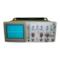
Tektronix 2235
229 pages
To Next Page IconTo Next Page
To Previous Page IconTo Previous Page
Page #39 background imageLoading...
Page #39 background image
T
heory
of
O
p
e
r
atio
n
-2235
Service
C
HA
NNEL
2
.
For
triggeri
ng
f r
om
C
h
annel
2,
t
h
e
Α
&
Β
ΙΝΤ
Sign
al
current
is
app
lie
d
to
t
he
emitters of
U
350D
an
d
switc
h
is
set
to
C
H
2
.
One
input
eac
h
of
U555C
and
U
555D
U
350
E
.
T
he
collector
curre
n
t
of
U
350D
is
converted
to
α
will
be
L
O
and
force
b
ot
h
gate
outputs
L
O
.
T
he L
O
from
voltage
across
feedbac
k
resistor
R357
.
T
he
o
pp
osite-p
h
ase
U555C
will
enable
t
he
C
h
a
n
nel
2
signal
pat
h
t
h
roug
h
U
335
collecto
r
current
of
U350
E
causes α
voltage
d
r
op
across
and
t
he
HI
out
p
uts
of
U555
B
and
U565C
will
disa
b
le
t
he
R
359
w
h
ic
h
adds
to
t
he
voltage
at
t
he
collecto
r
of
U
350C
.
C
h
annel
1
p
at
h
.
T
h
is
voltage
a
pp
ears
at
t
h
e
b
ase
of
U350A
w
h
ic
h bu
ffers
and
level
sh
ifts
t
he
sig
n
al
b
ac
k
to
0
V
.
T
he
emitter
sig
n
al
of
U350A
d
rives
t h
eΧ
-Axis
Am
p
lifier,
t
he
Β
Trigger
Ge
n
erator,
VER
T
M
OD
E
.
Wh
en
t
h
e
Α
&Β
ΙΝΤ
switc
h
is
set
to
VER
T
a
nd
t
he
b
ase
of
U350
B
.
T
h
e
emitter
signal
of
U350
B
in
turn
M
OD
E
,
trigger
sou
rce
selection
is
determined
by
t
he
two
d
rives
t
h
e
Α
Trigger
Generator
w
henever
C
R
372
is
forward
VER
TICA
L
M
OD
E
switc
h
es
.
F
or
all
VER
TIC
AL
M
OD
E
b
iased
.
switc
h
combi
n
ations
excep
t
BOTH-CHOP,
t
h
e
V
M
ode
Τ
line
is
HI
.
T
h
e
i
n
puts
and
o
u
tp
u
ts
of
U555
B
,
U555C, and
U555D
will
all
be
HI,
and
triggeri
ng
selection
will
t
hen be
d
etermi
ned by
t
he
in
p
uts
of
U
565
B
and
U
565C
t
h
at
are
con
-
trolled
by
U540A
in
t
he
C
h
ann
el
Switch
circuit
.
Α
E
xte
rn
al
Trigge
r
Am
p
lifier
Wh
en
C
h
an
n
el
1
is
selected
(
VER
TICA
L
M
OD
E
switc
h
set
to
C
H
1),
t
h
e
i
n
put
to
U565C
will
b
e
HI
.
T
he gate
out
p
ut
will
be
L
O
and
t
h
e
C
h
annel
1
signal
will
be
selecte
d
.
T
h
e
L
O
from
t
h
e
ot
h
er
outp
ut
of
U
540A
is
applied
to
U
565
B
and
causes
t
he
C
h 2
Trig
line
to
go
HI
a
nd
t
h
e
C
h
a
nn
el
2
Trigger
signal
is
disabled
.
Wh
e
n
C
h
a
nn
el
2
is
selected
(
VER
TICA
L
M
OD
E
switc
h
set
to
C
H
2),
t
he
o
u
tputs
of
U540A,
U565
B
,
and
U565C
will
b
e
t
h
e
reverse
of
t
h
e
states
d
escri
be
d
for
C
h
annel
1
selec-
tion
.
T
he
C
h
annel
2
signal
will
be
selected
and
t
h
e
C
h
a
nn
el
1
Trigger
signal
disa
b
led
.
Wh
e
n
selecti
n
g
A
L
T
VER
TICA
L
M
OD
E
,
t
he
in
p
uts
of
U565
B
and
U565C
will
toggle
wit
h
eac
h
swee
p
.
T
he outp
uts
of
t
h
e
two
gates
will
also
toggle
and
t
h
e
T
r
igger
sig
n
al
source
will
alternate
wit
h
t
h
e
displayed
c
h
an
n
el
.
In
t
h
e
ADD
VER
TICA
L
M
OD
Ep
osition,
b
ot
h
in
pu
ts
to
U565
B
and
U565C
will
be
HI
and
t
h
e
gate
out
p
uts
will
be
L
O
.
B
ot
h
C
h
annel
1
an
dC
hann
el
2
sig
n
al
p
at
h
s
will
be
en-
abled
and
t
h
ei
r
output
cur
r
en
t
will
be su
mme
d
at
t
h
e
inputs
of
t
he
Inte
r
nal
Trigger
Am
p
lifier
to
p
ro
du
ce
t
h
e
internal
trig-
ger
signal
.
T
he
C
H
O
P
VER
TICA
L
M
OD
E
p
osition
g
r
ounds
t
h
e
V
M
o
de
Τ
line
and
p
laces
α L
O
on an
in
p
ut of
b
ot
h
U
555
B
an
d
U555C
.
T
h
eou
t
pu
ts
of
t
hese
two
gates
will
t
h
en
b
e
L
O
and
t
he
sig
n
al
to
t
he
Internal
T
r
igger
Am
p
lifie
r
will
b
e
t
he
same
as
for
t
h
e
ADD
mode
.
I
n
ter
n
al
Trigger
Am
p
lifie
r
T
he
Internal
Trigger
Am
p
lifier
co
n
verts
t
h
e
d
ifferential
Transformer
Τ
390
in
t
h
e
Power
Su
pp
ly
p
rovides
α
line-
trigger
sig
n
als
from
t
h
e
V
e
r
tical
Pream
p
lifiers
into
α
si
n
gle-
fre
qu
ency
sig
n
al
t
h
roug
h
R
397
to
Q397
.
Diode
CR
399
is
ended
sig
n
al
t
h
at
drives
t
h
e
Χ
-Axis
Am
p
lifier
and
t
h
e
Α
and
forwar
d
b
iase
d
w
hen
S392
is in
t
he L
I
NE
p
ositio
n
,
and
t
h
e
Β
Trigger
Generators
.
emitter
sig
n
als
of
Q397
will
d
rive
t
h
e
Α
Trigger
Ge
n
erator
.
T
he
Α
External
Trigger
Amplifier
buffers
signals
a
pp
lied
to
t
he
ΕΧΤ
I
NPU
T
connector
to
drive
t
h
e
Α
Trigger
Genera-
tor
.
In
p
ut
signal
coup
ling
is
d
etermi
n
ed by
Α
ΕΧΤ
CO
U
-
PL
I
N
G
switc
h
S380
w
h
ic
h
selects
AC,
DC,
or
DC
-
10
coup
ling
.
Wh
en
S380
is
i
n
t
he
AC
position,
t
he
i
np
ut
signal
is
ac-
coupled
t
h
roug
h
C376
.
In
t
he
DC
positio
n
,
t
he
i
n
put
signal
is
connected
directly
to
t
he
Am
p
lifie
r
.
T
he
DC
-
10
position
attenuates
t
he
i
n
put
signal
b
y α
facto
r
of
10
t
hr
oug
h
t
he
com
pensated
divider
com
p
ose
d
of
R
377,
R378,
C380,
and
C381
.
T
he
signal
is
t
hen a
pp
lie
d
to
t
he gate
of
Q382A
.
T
h
is
source-follower
drives
emitter-follower
transistor
0384
w
h
ic
h
lowers
t
he
Am
p
lifier
o
u
t
pu
t
im
pe
d
ance
.
T
he
two
FETs
are
α
matc
h
ed
p
air,
an
d
since
t
he
gate
and
source
of
0382
Β
are
connected
toget
h
er,
0382
Β
will
s
upp
ly
so
ur
ce cu
rre
n
t
for
Q382A
suc
h
t
h
at
t
h
ere
will
b
e
no
voltage
d
ro
p
across
t
he
gate-source
j
u
n
ctio
n
of
Q382A
.
Protectio
n
-
d
io
de CR
381
clam
p
s
t
h
e
signal
at
t
he
gate
of
Q382A
to
about
-9
V
.
T
he
Am
p
lifier
o
u
t
p
ut
will
drive
t
h
e
Α
Trigger
Generator
t
h
roug
h
forward-
b
iased
C
R
393
w
h
e
n
ever
t
h
eΑ
SO
UR
C
E
switc
h
is
set
to
EXT
.
Wh
en
t
h
e
Α
SOUR
C
E
switc
h
is
not set
to
ΕΧΤ
,
t
h
e
base-emitter
j
unction
of
0384
will
be
reverse
b
iase
d
and
t
h
e
Am
p
lifier
will
be
disabled
.
L
ine
T
r
igge
r
Am
p
lifie
r
T
h
e
L
ine
Trigger
Am
p
lifier
supp
lies
α
li
n
e-fre
que
n
cy
trig-
ger
signal
to
t
he
Α
Trigger
Ge
n
erator
w
hen
t
h
e
Α
SOUR
C
E
switc
h
is
i
n
t
he
L
I
NE
p
ositio
n
.

Table of Contents

Other manuals for Tektronix 2235

Questions and Answers:

Question and Answer IconNeed help?

Do you have a question about the Tektronix 2235 and is the answer not in the manual?

Tektronix 2235 Specifications

General IconGeneral
BrandTektronix
Model2235
CategoryTest Equipment
LanguageEnglish

Related product manuals