EasyManuals Logo
Home>Tektronix>Test Equipment>2235

Tektronix 2235 User Manual

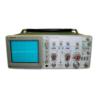
Tektronix 2235
229 pages
To Next Page IconTo Next Page
To Previous Page IconTo Previous Page
Page #96 background imageLoading...
Page #96 background image
TR
O
UBLE
S
H
OOTI
N
G
T
E
C
HN
IQ
UE
T
he
following
p
rocedure
is
a
r
ra
n
ge
d
i
n
an
order
t
h
at
en-
ab
les
check
ing
simp
le
trouble
p
ossi
b
ilities
b
efore
r
e
q
uiring
more
extensive
tro
ub
les
h
ooting
.
T
he
first
fou
r
checks
en-
sure
p
ro
p
er
control
settings,
co
nn
ections,
op
eration,
and
ad
j
ustme
n t
.
If
t
h
e
trouble
is
not
located
b
y
t
h
ese
c
h
ec
k
s,
t
he
remaini
n
g
ste
ps
will
aid
in
locati
ng
t
h
e
defective
com
pone
n
t
.
Wh
en
t
he
defective
com
p
onent
is
locate
d
,
re
p
lace
it,
using
t
h
eap
propriate
re
p
laceme
n
t
proce
d
ure
give
n un
der
"Cor-
rective
M
aintenance"
i
n
t
h
is
section
.
CA
U
TIO
N
I
n
correct control
setti
ngs
can
give
α
false
i
nd
icatio
n
of
i
nstrument
malfu
n
ction
.
If
t
h
ere
is
any
qu
estio
n
a
b
out
t
h
e
correct
function
or
o
p
eratio
n
of
any
cont
r
ol,
refer
to
eit
h
e
r
t
he
"Operating
Instr
u
ctio
n
s"
(Section
2)
in
t
h
is
ma
n
ual
or to
t
he
i
n
strument
O
p
erators
Manual
.
2
.
C
h
ec
k
Associate
d
Equ
i
p
me
n
t
To
avoid
electrical
s
h
oc
k
,
disconnect
t
he
instr
u
me
n
t
from
t
h
e
powe
r
-input
sou
r
ce
before
performing
vis
u
al
i
ns
p
ectio
n
.
3
.
V
isual
C
h
ec
k
W
A
RN
I
NG
W
A
RN
I
NG
Da
n
gerous
p
ote
n
tials
exist
at
several
p
oints
t
h
ro
ugh
-
out
t
h
is
instrument
.
If
it
is
o
p
erate
d
wit
h
t
he
ca
b
inet
removed,
do
not
touc
h
ex
p
ose
d
co
nn
ectio
ns o
r
components
.
4
.
C
h
ec
k
Instr
u
ment
P
erfo
r
ma
n
ce
a
nd
A
dju
stme
n
t
C
heck
t
he
p
erformance
of
eit
h
er
of
t
h
ose
circuits
w
here
trouble
a
pp
ears to
exist
or
t
h
e
entire
instr
u
ment
.
T
he
appar-
ent
trou
b
le
may
only
b
e
t
he
result
of
misad
j
ustment
.
Com-
p
lete
performance check
a
nd
ad
j
ustment
i
n
structions
are
give
n
in
Sectio
ns
4a
nd 5
of
t
h
is
manual
.
B
efo
r
e
using
a
ny
test
eq
u
i
p
ment
to
ma
ke
measure-
me
n
ts
on
static-se
n
sitive,
current-se
n
sitive,
o
r
volt-
age-sensitive
com
p
o
n
e
n
ts
or
assem
b
lies,
e
n
sure
t
h
at
an
y
voltage
or c
u
rre
n
t
sup
p
lied
by
t
he
test
equ
i
pme
n
t
5
.
Isolate
Trou
b
le to
α
Circuit
does
not
excee
d
th
e
limits
of
t
he component
to
be
tested
.
To
isolate
problems
to
α p
articular
area,
use
t
h
e
tro
u
ble
sym
p
tom
to
h
elp
identify
t
he
circuit
in
w
h
ic
h
t
he
trouble
is
locate
d
.
R
efer
to
t
he
tro
ub
les
h
ooting
c
h
arts
in
t
h
e
"Dia-
1
.
C
h
ec
k
Co
n
t r
ol
Setti
n
gs
grams"
section
as an
aid
in
locating
α
fa
u
lty
circ
u
it
.
6
.
C
h
ec
kP
ower
S
u
pp
lies
W
A
RN
I
NG
M
ai
n
te
n
a
n
ce-2235
Service
Befo
r
e
proceeding,
ensure
t
h
at
any
e
qu
i
p
me
n
t
used
wit
h
F
or
safety
r
easons
an
isolatio
n
transformer
m
u
st
b
e
t
h
is
instr
u
ment
is
o
p
erating
co
r
rectly
.
V
erify
t
h
at
input
sig-
con
n
ected
w
he
n
ever
trou
b
les
h
ooting
is
done
i
n
the
nals
are
p
ro
p
erly
co
nn
ected a
n
d
t
h
at
t
h
e
inte
r
connecting
P
rereg
u
lator
an
d
t
he
I
nverter
P
ower
Supply
sections
.
cables are
n
ot
d
efective
.
C
h
ec
k
t
h
e
power-i
n
put-sou
r
ce
voltages
.
C
h
eck
t
he
p
ower
sup
p
lies
w
h
enever
trouble
symptoms
appear
in
more
t
h
an
one
circuit
.
T
h
e
correct
out
p
ut
voltage
and
rip
p
le
for
eac
h su
p
p
ly
s
h
ould
be
measured
b
etwee
n
t
he
supp
ly
test
point
an
d
ch
assis
ground
(see
Ta
b
le
6-4 an
d
associate
d
circ
u
it
b
oa
rd
ill
u
stration)
.
V
oltages
may
be
mea-
sured
eit
h
er
b
y an
D
MM
or
an
oscillosco
p
e,
w
h
ile
t
he
ri
pp
le
measurements
are
accom
p
lis
hed
only
wit
h an
oscilloscope
.
B
efore
check
ing
p
ower-s
upp
ly
circ
u
itry
set
t
h
e
Α
INTENSI-
TY
control
to
minim
u
m
b
rig
h
tness
an
d
t
he
Α
S
E
C/DI
V
switc
h
to
Χ
-
Υ
mo
de
.
P
erfo
r
m
α
visual
ins
p
ectio
n
.
T
h
is
c
h
ec
k
may
r
eveal
bro-
k
en
connections
or
wires,
d
amage
d
compo
nen
ts,
semico
n
ductors
not
firmly
mo
un
te
d
,
damaged
circ
u
it
boar
d
s,
or
Wh
en measuring
ri
pp
le,
u
se
α
1
Χ
p
r
o
be
wit
h α
b
ayonet
ot
h
e
r
clues
.
signal
tip
attac
hed
to
t
he
pro
b
e
ti
p
to mi
n
imize
st
r
ay
pic
ku
p
.

Table of Contents

Other manuals for Tektronix 2235

Questions and Answers:

Question and Answer IconNeed help?

Do you have a question about the Tektronix 2235 and is the answer not in the manual?

Tektronix 2235 Specifications

General IconGeneral
BrandTektronix
Model2235
CategoryTest Equipment
LanguageEnglish

Related product manuals