Specif ication-2465 Operators
Table
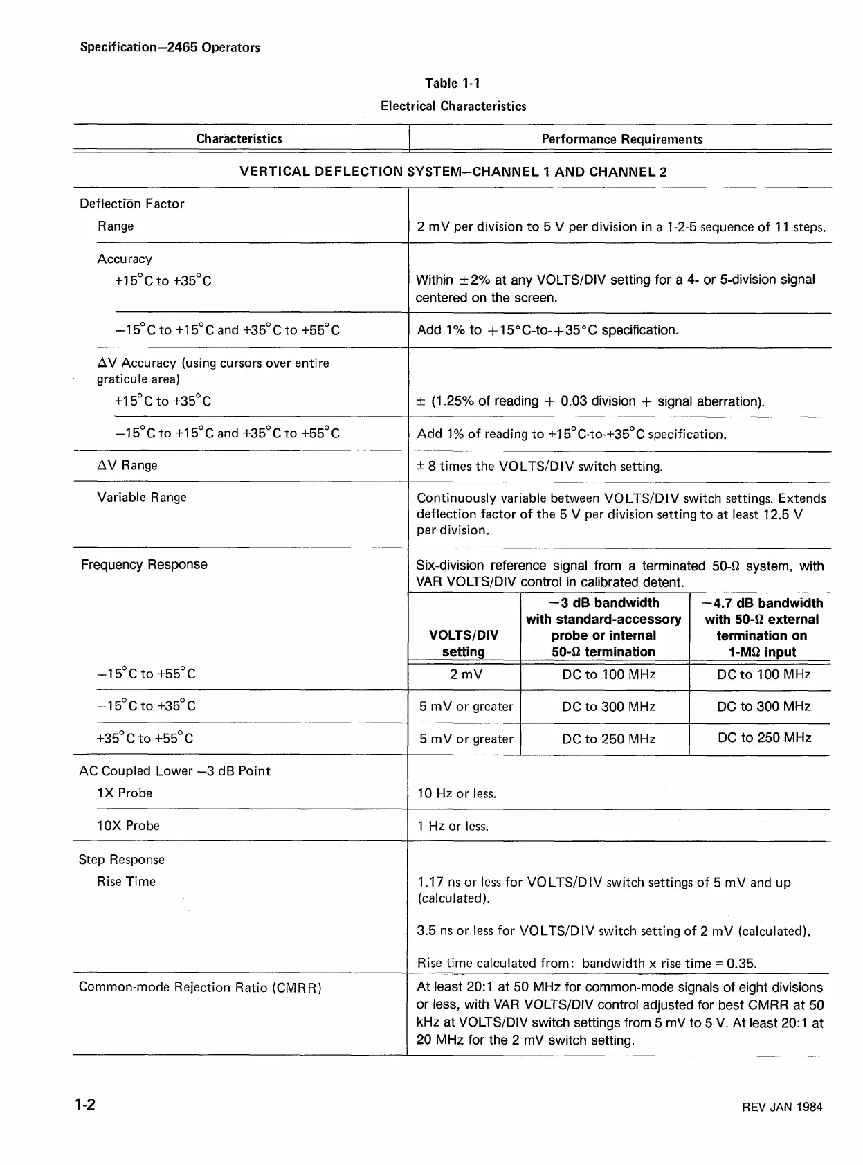
1-1
Electrical Characteristics
VERTICAL DEFLECTION SYSTEM-CHANNEL
1
AND CHANNEL
2
Characteristics
DeftectEn Factor
Range
Performance Requirements
2 mV per division to 5 V per division in
a
1-2-5 sequence of 11 steps.
Accuracy
+I
5"
c
to +35O
c
Within
_+2%
at any VOLTSIDIV setting for a
4-
or 5-division signal
centered on the screen.
-15°C to +15"C and +35"C to +55"C Add 1
%
to
+
1
5
O
C-to-
+
35
O
C specification.
AV Accuracy (using cursors over entire
graticule area)
+I
5°C to +35OC
+
(1.25% of reading
+
0.03 division
+
signal aberration).
-1 5"
c
to
+I
5"
c
and +35"
c
to +55"
c
Add 1
%
of reading to
+I
5°~-to-+350~ specification.
AV Range
---
+
8
times the VOLTSIDIV switch setting.
Variable Range
Continuously variable between VOLTSIDIV switch settings. Extends
deflection factor of the 5 V per division setting to at least 12.5 V
per division.
Frequency Response
-1 5'~ to +55"~
2 mV
I
DCto 100 MHz
I
DCto 100 MHz
Six-division reference signal from
a
terminated 504 system, with
VAR VOLTSIDIV control in calibrated detent.
VOLTSIDIV
setting
AC Coupled Lower -3 dB Point
1
X Probe
5 mV or greater
5
mV or greater
10
Hz
or
less.
-3
dB bandwidth
with standard-accessory
probe or internal
50-SZ termination
1 OX Pro be
-4.7
dB bandwidth
with 50-SZ external
termination on
1-MO
input
DC to 300 MHz
DC to 250
MHz
1 Hz or
less.
-
-
--
DC to 300 MHz
DC
to 250 MHz
Step Response
Rise Time
1.17 ns or
less
for VO LTSID IV switch settings of 5 mV and up
(calculated).
3.5 ns or less for VOLTSIDIV switch setting of 2
mV (calculated).
.Rise time calculated from: bandwidth x rise time
=
0.35.
Common-mode Rejection Ratio (CM R R)
At least 20:1 at 50 MHz for common-mode signals of eight divisions
or less, with VAR VOLTSIDIV control adjusted for best CMRR at 50
kHz at VOLTSIDIV switch settings from 5 mV to 5 V. At least 20:1 at
20
MHz for the 2 mV switch setting.
REV
JAN
1984

 Loading...


