Basic Applications-2465 Operators
NOTE
In certain situations, such as checking test limits,
it
may be more convenient to use the cursors in the
Tracking mode. To activate Tracking mode, push in
the TRACKING button at the same time that
AV
is selected (step
7).
In
this mode, the
A
REF OR
DL
Y
POS control will mu ve both cursors equally
at the same time. The
A
control will continue to
move the Delta cursor independently and can be used
to preset a desired voltage-ratio test limit. The
A
REF
OR DL
Y
POS control can then be used to position
the test limits (cursors) either on various test signals
or on various portions of a test signal.
ALGEBRAIC ADDITION
AND ELIMINATING
COMMON-MODE SIGNALS
With the ADD VERTICAL MODE button pressed in,
the waveform displayed
is
the algebraic sum of the signals
applied to the CH 1 OR
X
and the CH 2 input connectors
(CH 1
+
CH
2).
If the INVERT push button
is
pressed in,
the waveform displayed
is
the difference between the
signals applied to the Channel 1 and Channel
2
inputs
(CH 1
-
CH
2).
When both VOLTSIDIV switches are
set
to the same deflection factor, the ADD trace deflection
factor
is
equal to the deflection factor indicated by either
VOLTSID IV switch.
Two common uses for ADD mode are: (1) the providing
of
a
dc offset for an ac signal riding on top of a high dc
level and (2) the canceling out of undesirable signal com-
ponents through common-mode rejection.
NOTE
The following general precautions should be observed
when using ADD mode.
I.
Do not exceed the input-voltage rating of the
oscilloscope or probe.
2.
Do not apply signals that exceed the equivalent of
about eight times the VO L TS/D
I
V
switch settings,
since large voltages may distort the display. For
example, with a
VOL TS/D I V switch setting of
0.5,
the voltage applied to that channel should not exceed
4
v.
3.
Use Channel
I
and Channel
2
POSITION control
settings which most nearly position the signal on each
channel to midscreen, when viewed separately. This
ensures the greatest dynamic range for ADD mode
operation.
4.
To attain similar responses from both channels, set
both the Channel
1
and the Channel
2
Input Coupling
switches to the same position.
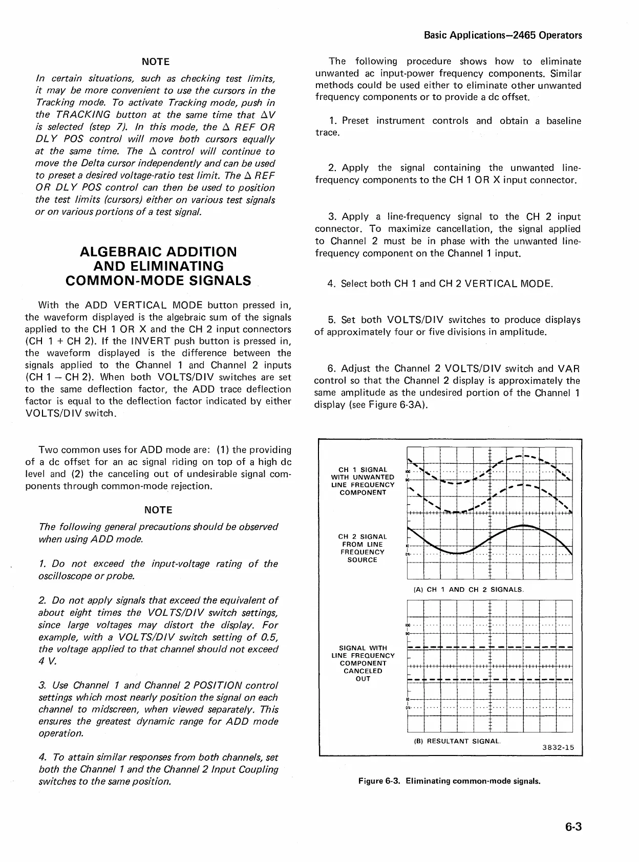
The following procedure shows how to eliminate
unwanted ac input-power frequency components. Similar
methods could be used either to eliminate other unwanted
frequency components or to provide
a
dc offset.
1. Preset instrument controls and obtain
a
baseline
trace.
2. Apply the signal containing the unwanted line-
frequency components to the CH 1 OR
X
input connector.
3. Apply
a
line-frequency signal to the CH 2 input
connector. To maximize cancellation, the signal applied
to Channel 2 must be in phase with the unwanted line-
frequency component on the Channel 1 input.
4.
Select both CH 1 and CH 2 VERTICAL MODE.
5.
Set both VOLTSIDIV switches to produce displays
of approximately four or five divisions in amplitude.
6. Adjust the Channel
2
VOLTSIDIV switch and VAR
control so that the Channel 2 display
is
approximately the
same amplitude
as
the undesired portion of the Channel 1
display
(see
Figure 6-3A).
CH
1
SIGNAL
WlTH
UNWANTED
LlNE FREQUENCY
COMPONENT
CH
2
SIGNAL
FROM
LlNE
FREQUENCY
SOURCE
(A)
CH
1
AND
CH
2
SIGNALS.
SIGNAL
WlTH
LlNE FREQUENCY
COMPONENT
CANCELED
OUT
(B)
RESULTANT
SIGNAL
Figure
6-3.
Eliminating common-mode signals.

 Loading...


