Section
3-2465
Operators
CONTROLS, CONNECTORS,
AND INDICATORS
The following descriptions are
intended to familiarize
the operator with the location and function of the instru-
ment's controls, connectors, and indicators.
POWER AND DISPLAY
Refer to Figure 3-1 for location of items 1 through
9.
@
INTENSITY Control-Adjusts brightness of the crt
trace display. This control does not affect intensity of
the crt readout display.
@)
BEAM FIND Switch-When held in, compresses the
display to within the graticule area. Aids the operator
in locating off-screen displays.
@
FOCUS Control-Adjusts the display for optimum
definition.
@
TRACE ROTATION Control-Operator-adjusted
screwdriver control used to align the crt trace with
the horizontal graticule lines. Once adjusted,
it
does
not require readjustment during normal operation of
the instrument.
READOUT
l
NTENSITY Control-Adjusts the inten-
sity of the crt readout display. This control
is
also
used to either enable or disable the scale-factor
display. Setting the control to MIN reduces the
readout intensity to minimum. Clockwise rotation
from midrange increases the readout intensity and
enables the scale-factor display; counterclockwise
rotation from midrange also increases the intensity
but disables the scale-factor display. Delta Volts and
Delta Time readouts and control messages will
continue to be enabled even when the scale-factor
display
is
disabled.
ASTlG Control-Operator-adjusted screwdriver con-
trol used in conjunction with the FOCUS control to
obtain
a
well-defined display over the entire graticule
area. Once adjusted,
it
does not require readjustment
during normal operation of the instrument.
@
SCALE ILLUM Control-Adjusts the light level of
the graticule illumination.
@
POWER Switch-Turns instrument power on and off.
Press in for ON; press again for OFF. An internal
indicator in the switch shows green when the switch
is
on and black when
it
is
off. Front-panel settings
that were unchanged for
at
least 10 seconds prior to
power-off will be returned when power
is
reapplied to
the instrument.
@
CRT-Has an 80-mm vertical and 100-mm horizontal
display area. Internal graticule lines eliminate parallax-
viewing error between the trace and the graticule
lines. Rise-time measurement points are indicated
at
the left edge of the graticule.
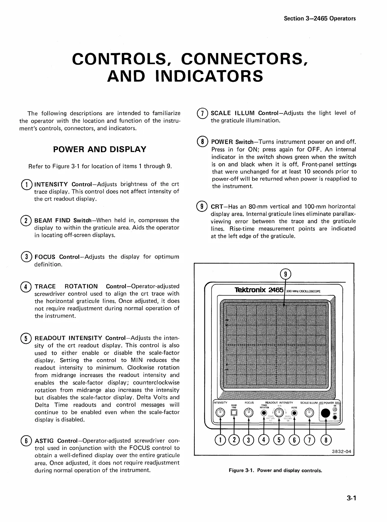
Figure
3-1.
Power and display controls.

 Loading...


