Section
6-2465
Operators
BASIC APPLICATIONS
The TEKTRON IX 2465 Oscilloscope provides an
accurate and flexible measurement system. After becoming
familiar with the controls, indicators, operating consider-
ations, and capabilities of the instrument, an operator can
easily develop his own convenient methods for making
particular measurements. The information in this section
is
designed to enhance operator understanding and to
assist
in
developing efficient techniques for making your specific
measurements. Recommended methods for making the
basic types of measurements with the 2465 are described
in the procedures contained in this section.
When
a
procedure first calls for presetting instrument
controls and
obtaining
a
baseline trace, refer to "Initial
Setup" in Section 5, "Operator's Checks and Adjustments."
INDEX OF PROCEDURES
Voltage Measurement.
......................
6-1
Voltage Ratio.
...........................
6-2
Algebraic Addition and Eliminating
Common-mode Signals.
.....................
6-3
Time Interval
............................
6-4
Frequency.
.............................
6-4
Time Difference Between Two Time-related Pulses
...
6-5
Time Ratio.
.............................
6-5
Phase Difference Between Two Time-related Signals.
..
6-6
Small-angle Phase Difference
..................
6-6
Delayed-sweep Operation
....................
6-7
VOLTAGE MEASUREMENT
The 2465 has a built-in Delta Volts function that
reduces voltage measurement to
a
simple process. The
following procedure may be used to make voltage measure-
ments between any two points on
a
waveform (e.g., ac
peak-to-peak voltages, instantaneous voltage levels, and
pulse heights).
1.
Preset instrument controls and obtain
a
baseline trace.
2. Aplply the signal to either the CH 1 OR
X
or the
CH
2
input connector and select the VE RTlCAL MODE switch
to display the channel used.
that the VOLTSIDIV VAR control
is
in the calibrated
detent.
4. Adjust the A TRIGGER LEVEL control to obtain
a
stable display.
5. Set the A SECIDIV switch to
a
position that displays
a few cycles of the waveform.
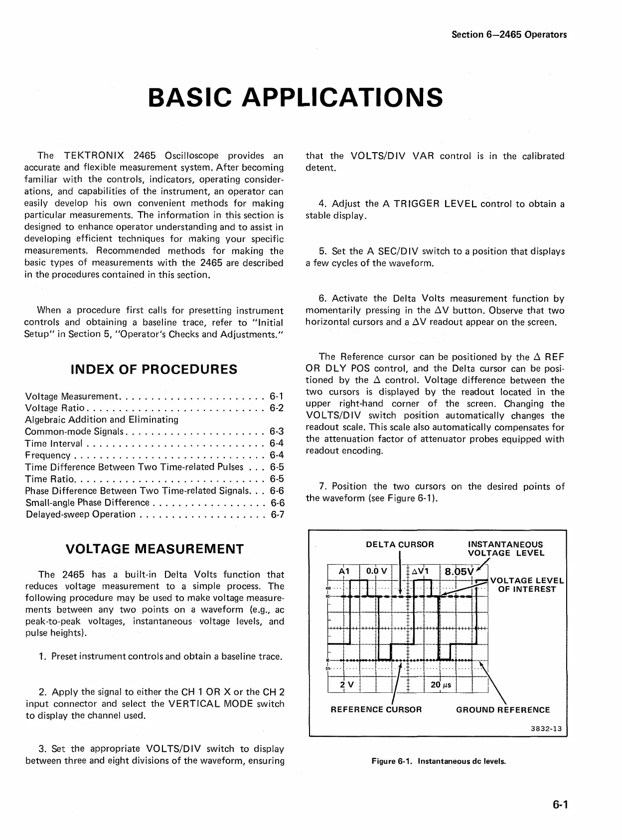
6. Activate the Delta Volts measurement function by
momentarily pressing in the AV button. Observe that two
horizontal cursors and
a
OV
readout appear on the screen.
The Reference cursor can be positioned by the A REF
OR DLY POS control, and the Delta cursor can be posi-
tioned by the A control. Voltage difference between the
two cursors
is
displayed by the readout located in the
upper right-hand corner of the screen. Changing the
VO LTSID IV switch position automatically changes the
readout scale. This scale also automatically compensates for
the attenuation factor of attenuator probes equipped with
readout encoding.
7. Position the two cursors on the desired points of
the waveform (see Figure 6-1
).
DELTA CURSOR INSTANTANEOUS
I
VOLTAGE LEVEL
TAG
E
INTE
LEVEL
.REST
REFERENCE CURSOR GROUND REFERENCE
3832-13
3. Set the appropriate VOLTSIDIV switch to display
between three and eight divisions of the waveform, ensuring
Figure
6-1.
Instantaneous
dc
levels.

 Loading...


