Controls, Connectors, and Indicators-2465 Operators
CALIBRATOR Connector-Provides
a
0.4-V
p-p
square-wave signal into
a
1-MS2 load,
a
0.2-V p-p
square-wave signal
into
a
5042 dc-coupled load, or
an 8-mA p-p square-wave current signal into
a
short
circuit
at
a
sweep
speed of 1 ms per division. The
CALIBRATOR output signal
is
useful for checking
the sweep, the delays, and the vertical deflection
accuracies, as well
as
compensating voltage probes
and checking the accuracy of current probes. The
repetition rate of the square wave changes with the
setting of the A SECIDIV switch. For all sweep-speed
settings from 100 ms per division to 100 ns per
division, the A Sweep display,
as
seen on the instru-
ment supplying the CALIBRATOR signal, will be
five cycles per 10 divisions. At 100 ms per division
and slower, the CALIBRATOR frequency will be
5 Hz; at 100 ns per division and faster, the frequency
will be 5 MHz. The signal amplitude
at
5 MHz will be
at
least 50% of the signal amplitude obtained when
the sweep speed
is
set
to 1 ms per division.
NOTE
Due to internal circuitry constraints, the
calibrator signal
is
not synchronized during
trace holdoff. This does not affect the accuracy
of the calibrator signal that is present during
a trace display. However, if the 2465
CA
L
I-
BRA TOR signal is used to calibrate other
instruments, the sweep of the 2465 must be
shut off. If
it
is not, the signal will appear to
jitter and will give false (low) frequency counts.
The sweep of the 2465 is easily shut off by set-
ting the TRIGGER MODE switch to SGL SEQ.
@
Auxiliary Ground Jack-Provides an auxiliary signal
ground when
interconnecting equipment under test
and the oscilloscope. Hookup
is
made via
a
banana-tip
connector.
HORIZONTAL AND
DELTA MEASUREMENT
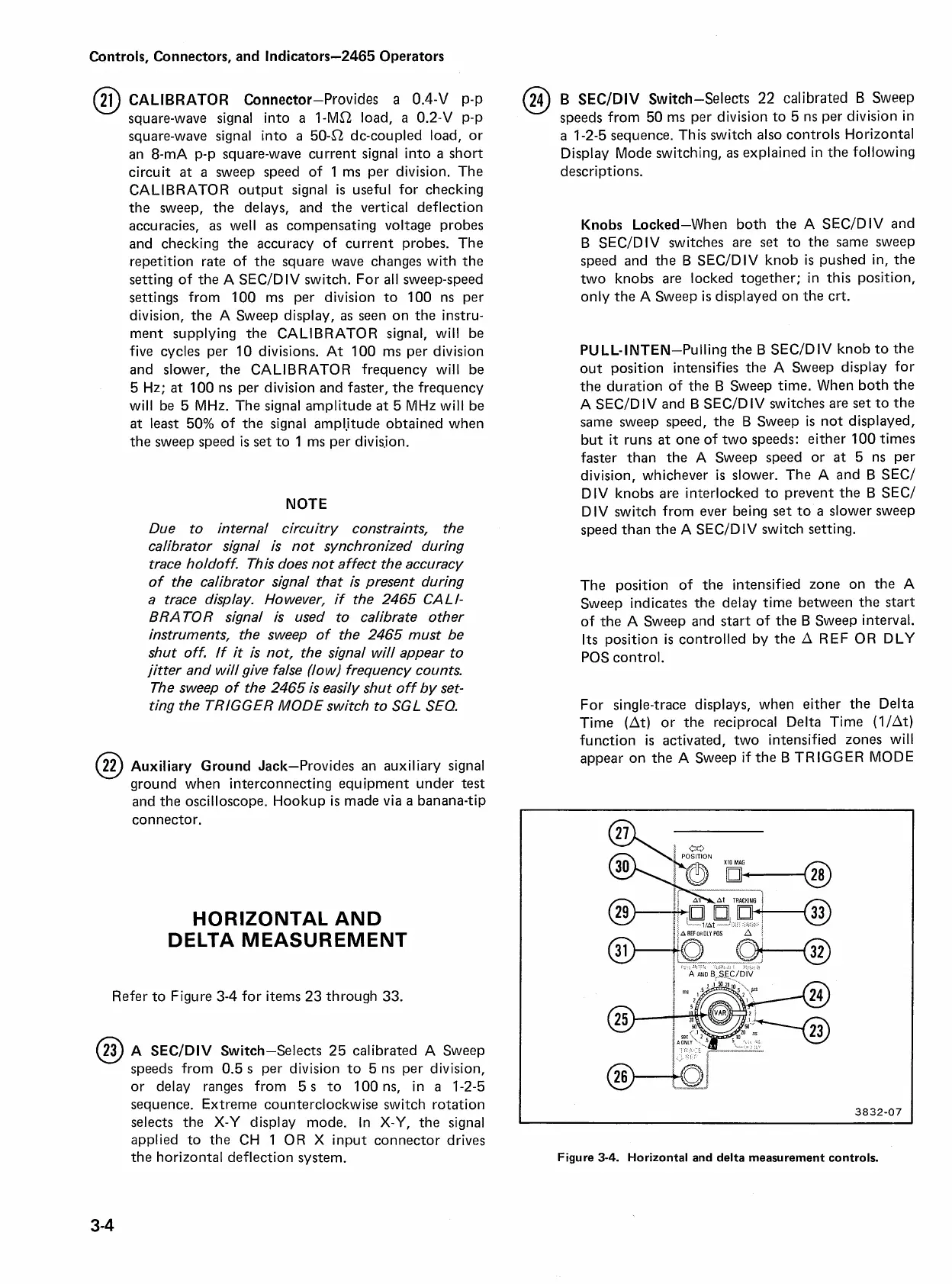
Refer to Figure 3-4 for items 23 through 33.
@
A SECIDIV Switch-Selects 25 calibrated A Sweep
speeds from 0.5
s
per division to 5 ns per division,
or delay ranges from
5
s
to 100 ns, in
a
1-2-5
sequence. Extreme counterclockwise switch rotation
selects the X-Y display mode. In X-Y, the signal
applied to the CH 1 OR X input connector drives
the horizontal deflection system.
@
B SECIDIV Switch-Selects
22
calibrated
B
Sweep
speeds from 50 ms per division to 5 ns per division in
a 1-2-5 sequence. This switch also controls Horizontal
Display Mode switching, as explained in the following
descriptions.
Knobs Locked-When both the A SECIDIV and
B
SECIDIV switches are set to the same sweep
speed and the B SECIDIV knob
is
pushed in, the
two knobs are locked together; in this position,
only the A Sweep
is
displayed on the crt.
PULL-INTEN-Pulling the B SECIDIV knob to the
out position intensifies the A Sweep display for
the duration of the
B
Sweep time. When both the
A SECIDIV and B SECIDIV switches are set to the
same sweep speed, the B Sweep
is
not displayed,
but
it
runs
at
one of two speeds: either 100 times
faster than the A Sweep speed or at 5 ns per
division, whichever
is
slower. The A and B SECI
DIV knobs are interlocked to prevent the B SECI
DIV switch from ever being
set
to a slower sweep
speed than the A SECIDIV switch setting.
The position of the intensified zone on the A
Sweep indicates the delay time between the start
of the A Sweep and start of the B Sweep interval.
Its position
is
controlled by the A REF OR DLY
POS control.
For single-trace displays, when either the Delta
Time (At) or the reciprocal Delta Time
(l/At)
function
is
activated, two intensified zones will
appear on the A Sweep if the B TRIGGER MODE
Figure
3-4.
Horizontal and delta measurement controls.

 Loading...


