Controls, Connectors, and Indicators-2465 Operators
MODE Switches-Select the indicated channel(s)
for display when latched in. Any combination of the
five possible signal selections can be displayed by
pressing in the appropriate push buttons. The Chan-
nel
1
signal will be displayed if none of the MODE
switches are latched in.
The algebraic sum of Channel
1
and Channel
2
is
displayed when the ADD push button
is
latched in.
When both ADD and INVERT buttons are latched in,
the waveform displayed
is
the difference between the
Channel 1 and Channel 2 signals. The INVERT
button also inverts the polarity of the signal output
at
the CH
2
SIG OUT connector on the rear panel.
At the same time, the Channel 2 trigger-signal
polarity
is
inverted so that if CH 2
is
selected
as
the
TRIGGER SOURCE, the displayed slope will agree
with the TRIGGER SLOPE switch setting.
When multiple channels are selected, they are dis-
played sequentially in order of priority. The estab-
lished priority order
is:
CH 1, CH 2, ADD, CH 3,
then CH
4.
POSITION Controls-Set vertical position of the
Channel 1 and Channel 2 signal displays. Clockwise
rotation of
a
control moves the associated trace
upward. When the
X-Y
display feature
is
in use,
Channel
1
POSITION control moves the display
horizontally; clockwise moves
it
to the right. The
Channel 2, Channel 3, and Channel
4
vertical POSI-
TION controls move the associated
X-Y
display
vertically.
@
CHOP-OUT: ALT Switch-Selects the vertical display
mode for multiple-channel displays.
CHOP (latched in)-When more than one channel
is selected, the vertical display switches sequen-
tially through the selected channels at the
chop-
switching rate.
The chop frequency changes between
1
MHz and
2.5
MHz, depending on the SECIDIV switch
setting. At all sweep speeds, the chop-switching
rate
is
desynchronized with the sweep frequency
to minimize waveform breaks when viewing
repetitive signals.
OUT: ALT (released out)-When more than one
channel
is
selected, the vertical display switches
sequentially through the selected channels. Alter-
nate switching occurs during sweep-retrace times.
If both A and
B
Sweeps are displayed, alternate
switching occurs
at
the completion of the B Sweep.
The position of this switch has no effect on the
switching rate of multiple
X-Y
displays. When more
than one
X-Y
display
is
selected, switching occurs
at
2.5 MHz.
@
20
MHz
BW
LIMIT Switch-Reduces upper 3 dB
bandpass of the vertical deflection system to
a
limit
of 13 to 24 MHz when latched in. Full instrument
bandwidth
is
available when push button
is
out.
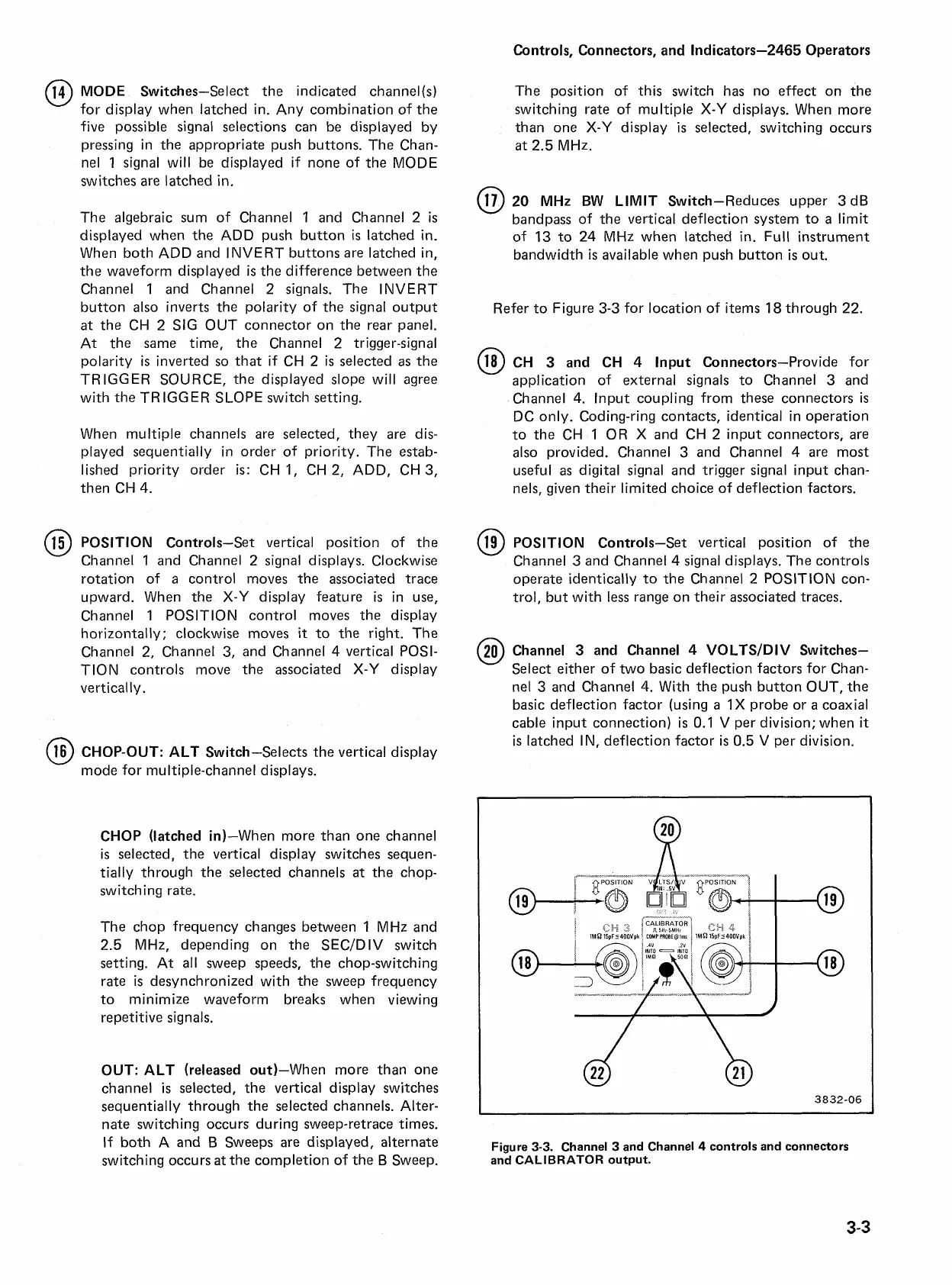
Refer to Figure 3-3 for location of items
18
through 22.
CH
3
and CH
4
lnput Connectors-Provide for
application of external signals to Channel 3 and
Channel
4.
lnput coupling from these connectors
is
DC only. Coding-ring contacts, identical in operation
to the CH 1
OR
X
and CH 2 input connectors, are
also provided. Channel 3 and Channel
4
are most
useful
as
digital signal and trigger signal input chan-
nels, given their limited choice of deflection factors.
@
POSITION Controls-Set vertical position of the
Channel 3 and Channel
4
signal displays. The controls
operate identically to the Channel
2
POSITION con-
trol, but with less range on their associated traces.
@
Channel
3
and Channel
4
VOLTSIDIV Switches-
Select either of two basic deflection factors for Chan-
nel 3 and Channel
4.
With the push button OUT, the
basic deflection factor (using
a
1X
probe or
a
coaxial
cable input connection)
is
0.1 V per division; when
it
is
latched IN, deflection factor
is
0.5 V per division.
Figure
3-3.
Channel
3
and Channel
4
controls and connectors
and CALIBRATOR output.

 Loading...


