Basic
Applications-2465
Operators
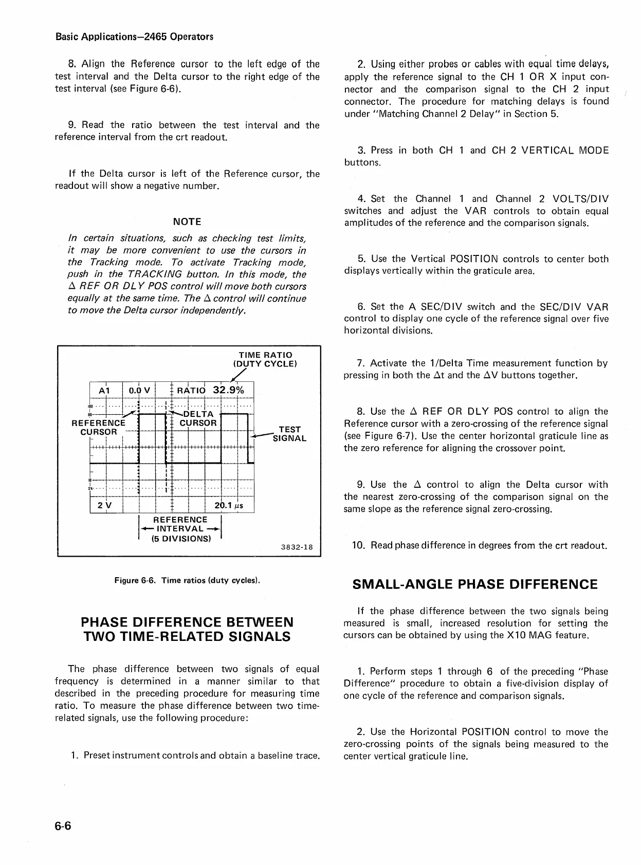
8.
Align the Reference cursor to the left edge of the
test interval and the Delta cursor to the right edge of the
test
interval (see Figure 6-6).
2.
Using either probes or cables with equal time delays,
apply the reference signal to the CH
1
OR
X
input con-
nector and the comparison signal to the CH
2
input
connector. The procedure for matching delays
is
found
under "Matching Channel
2
Delay" in Section
5.
9.
Read the ratio between the
test
interval and the
reference interval from the crt readout.
3.
Press in both CH
1
and CH
2
VERTICAL MODE
buttons.
If the Delta cursor is left of the Reference cursor, the
readout will show
a
negative number.
NOTE
In certain situations, such as checking test limits,
it
may be more convenient to use the cursors in
the Tracking mode. To activate Tracking mode,
push in the TRACKING button. In this mode, the
A
REF
0
R DL
Y
POS
control will move both cursors
equally at the same time. The
A
control will continue
to move the Delta cursor independently.
TIME RATIO
(DUTY CYCLE)
TEST
;IGNAL
REFERENCE
c-
INTERVAL
--,
(5
DIVISIONS)
3832-18
Figure
6-6.
Time ratios (duty cycles).
PHASE DIFFERENCE BETWEEN
TWO TIME-RELATED SIGNALS
The phase difference between two signals of equal
frequency
is
determined in
a
manner similar to that
described in the preceding procedure for measuring time
ratio. To measure the phase difference between two time-
related signals, use the following procedure:
1.
Preset instrument controls and obtain
a
baseline trace.
4.
Set the Channel
1
and Channel
2
VOLTSIDIV
switches and adjust the VAR controls to obtain equal
amplitudes of the reference and the comparison signals.
5.
Use the Vertical POSITION controls to center both
displays vertically within the graticule area.
6. Set the A
SECIDIV switch and the SECIDIV VAR
control to display one cycle of the reference signal over five
horizontal divisions.
7. Activate the 11Delta Time measurement function by
pressing in both the At and the AV buttons together.
8.
Use the
A
REF
OR DLY POS control to align the
Reference cursor with
a
zero-crossing of the reference signal
(see Figure 6-7). Use the center horizontal graticule line
as
the zero reference for aligning the crossover point.
9.
Use the A control to align the Delta cursor with
the nearest zero-crossing of the comparison signal on the
same slope
as
the reference signal zero-crossing.
10.
Read phase difference in degrees from the crt readout.
SMALL-ANGLE PHASE DIFFERENCE
If the phase difference between the two signals being
measured
is
small, increased resolution for setting the
cursors can be obtained by using the
XI0
MAG feature.
1.
Perform steps
1
through 6 of the preceding "Phase
Difference" procedure to obtain
a
five-division display of
one cycle of the reference and comparison signals.
2.
Use the Horizontal POSITION control to move the
zero-crossing points of the signals being measured to the
center vertical graticule line.

 Loading...


