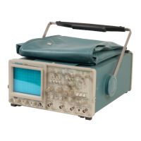
Operating Considerations-2465 Operators
SIGNAL CONNECTIONS
Probes
Generally, probes offer the most convenient means of
connecting an input signal to the instrument. Shielded
to prevent pickup of electromagnetic interference, the
standard 1 OX probes supplied with this instrument offer
a high input impedance that minimizes circuit loading. This
allows the circuit under test to operate with
a
minimum of
change from the normal, unloaded condition. Also, the
subminiature body of these probes has been designed for
ease of use either when probing circuitry containing close
lead spacing or when probing in a confined space.
Both the probe itself and the probe accessories should
be handled carefully at all times to prevent damage. Avoid
dropping the probe body. Striking a hard surface can cause
damage to both the probe body and the probe tip. Exercise
care to prevent the cable from being crushed or kinked.
Do not place excessive strain on the cable by pulling.
The standard-accessory probe
is
a compensated 10X
voltage divider.
It
is
a
resistive voltage divider for low
frequencies and a capacitive voltage divider for high-
frequency signal components. Inductance introduced by
either
a
long signal or ground lead forms
a
series-resonant
circuit. This circuit will affect system bandwidth and will
ring if driven by a signal containing significant frequency
components
at
or near the circuit's resonant frequency.
Oscillations (ringing) can then appear on the oscilloscope
display and distort the true signal waveform. Always keep
both the ground lead and the probe signal-input connec-
tions
as
short
as
possible to maintain the best waveform
fidelity.
Misadjustment of probe compensation
is
a
common
source of measurement error. Due to variations in oscillo-
scope input characteristics, probe compensation should
be checked and adjusted, if necessary, whenever the probe
is
moved from one oscilloscope to another or between
channels of a multichannel oscilloscope. See the procedure
in Section
5,
"Operators's Checks and Adjustments," or
consult the probe instruction manual.
Coaxial Cables
Cables may also be used to connect signals to the input
connectors, but they may have considerable effect on the
accuracy of
a
displayed waveform. To maintain the original
frequency characteristics
of
an
quality, low-loss coaxial cables
cables should be terminated
at
acteristic impedance. If this
is
impedance-matching devices.
applied signal, only high-
should be used. Coaxial
both ends in their char-
not possible, use suitable
INPUT-COUPLING CAPACITOR
PRECHARGING
When the input coupling switch
is
set
to GND, the input
signal
is
connected to ground through the input-coupl ing
capacitor in series with a I-Ma resistor to form
a
pre-
charging network. This network allows the input-coupling
capacitor to charge to the average dc voltage level of the
signal applied to the probe. Thus, any large voltage tran-
sients that may accidentally be generated will not be
applied to the amplifier input when input coupling
is
switched from GND to
AC.
The precharging network also
provides
a
measure of protection to the external circuitry
by reducing the current levels that can be drawn from the
external circuitry during capacitor charging.
EXTERNAL TRIGGERING
Both the
A
and the
B
trigger signals may be independ-
ently obtained from any of the four vertical input channels.
When viewing signals that require
a
trigger source different
from one of the displayed vertical signals (traditionally
referred to
as
"external triggering"), any free vertical
channel may be used to input
a
trigger signal. The signal
can be viewed on the crt to aid in setting the trigger circuit
controls by selecting that respective channel for the vertical
display (replaces the usual "trigger view" feature). After
establishing the correct triggering, the trigger signal display
can then be removed from the vertical signal display or
allowed to remain,
at
the operator's descretion.
Channel 1 and Channel
2
can condition
a
wide range of
signals to produce triggers-over the full vertical deflection
range of the channel from millivolts to hundreds of volts
in amplitude. Channel
3
and Channel
4
inputs have
a
much
more limited choice of vertical deflection ranges available
(0.1 volt and 0.5 volt per division without external attenu-
ation) and are more useful for digital signal amplitudes.
However, signals much larger can be processed, provided
they do not exceed the maximum-rated signal amplitude
for the input.

 Loading...