Controls, Connectors, and Indicators-2465 Operators
CH
2
SIGNAL
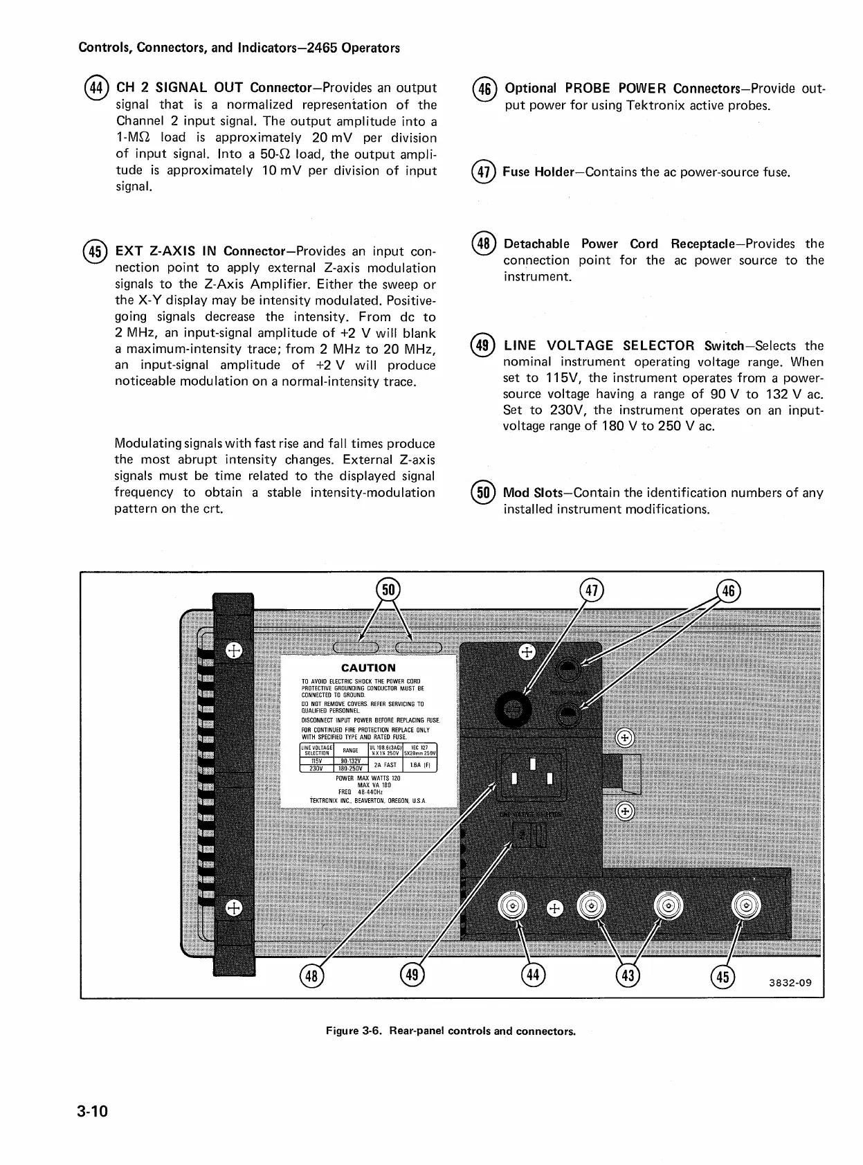
OUT Connector-Provides an output
signal that
is
a
normalized representation of the
Channel 2 input signal. The output amplitude into
a
I-Ma load
is
approximately 20 mV per division
of input signal. Into
a
5042 load, the output ampli-
tude
is
approximately 10 mV per division of input
signal.
EXT Z-AXIS IN Connector-Provides an input con-
nection point to apply external Z-axis modulation
signals to the
2-Axis Amplifier. Either the sweep or
the
X-Y
display may be intensity modulated. Positive-
going signals decrease the intensity. From dc to
2 MHz, an input-signal amplitude of +2 V will blank
a
maximum-intensity trace; from 2 MHz to 20 MHz,
an input-signal amplitude of +2V will produce
noticeable modulation on
a
normal-intensity trace.
Modulating signals with fast rise and fall times produce
the most abrupt intensity changes. External Z-axis
signals must be time related to the displayed signal
frequency to obtain
a
stable intensity-modulation
pattern on the crt.
@
Optional PROBE POWER Connectors-Provide out-
put power for using Tektronix active probes.
@
Fuse Holder-Contains the ac power-source fuse.
@
Detachable Power Cord Receptacle-Provides the
connection point for the ac power source to the
instrument.
@
LINE VOLTAGE SELECTOR Switch-Selects the
nominal instrument operating voltage range. When
set to 11 5V, the instrument operates from
a
power-
source voltage having a range of 90 V to 132
V
ac.
Set to 230V, the instrument operates on an input-
voltage range of 180
V
to 250 V ac.
@
Mod Slots-Contain the identification numbers of any
mstalled instrument modifications.
I
Figure
3-6.
Rear-panel controls and connectors.

 Loading...


