Basic Applications-2465 Operators
TlME DIFFERENCE BETWEEN
lWO
TIME-RELATED PULSES
The time difference between two time-related pulses
can be measured in
a
manner similar to that previously
described for measuring time interval.
1.
Using either probes or cables with equal time delays,
connect one signal to the CH
1
OR
X
input connector and
the other signal to the
CH
2
input connector. The pro-
cedure for matching probe delays
is
found under "Matching
Channel
2
Delay" in Section 5, "Operator's Checks and
Adjustments."
2.
Select both CH
1
and CH
2
VERTICAL MODE
switches.
TlME
RATIO
The Delta Time function also can be used to measure
and compute the ratio, in terms of percent, between two
different time intervals (e.g., a
test
interval and
a
reference
interval used to measure a duty cycle). To measure a time
ratio, use the following procedure:
1.
Preset instrument controls and obtain
a
baseline trace.
2.
Apply the reference signal to either the CH
1
OR
X
or the CH
2
input connector and select the VERTICAL
MODE switch to display the channel used.
3.
Set the appropriate VOLTS/DIV switch for a con-
venient amplitude display of the waveform.
4.
Adjust the A TRIGGER LEVEL control to obtain a
stable display.
3.
Set TRIGGER controls so that either one (but not
both) of the signals or
a
third time-related signal
is
the
triggering signal source.
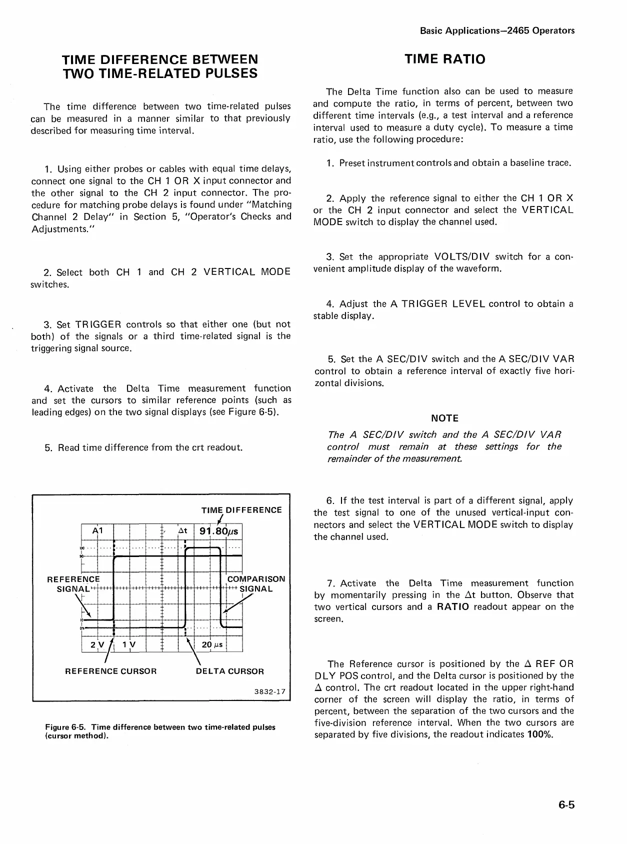
4.
Activate the Delta Time measurement function
and
set
the cursors to similar reference points (such
as
leading edges) on the two signal displays (see Figure 6-5).
5. Read time difference from the crt readout.
TIME, DIFFERENCE
REFERENCE CURSOR DELTA CURSOR
3832-17
Figure
6-5.
Time difference between two time-related pulses
(cursor method).
5. Set the A SECIDIV switch and the A SECIDIV VAR
control to obtain
a
reference interval of exactly five hori-
zontal divisions.
NOTE
The
A SEC/DIV
switch and the
A SEC/DI V VA
R
control must remain at these settings for the
remainder of the measurement.
6. If the
test
interval
is
part of
a
different signal, apply
the test signal to one of the unused vertical-input con-
nectors and select the VERTICAL MODE switch to display
the channel used.
7.
Activate the Delta Time measurement function
by momentarily pressing in the At button. Observe that
two vertical cursors and a RATIO readout appear on the
screen.
The Reference cursor
is
positioned by the A REF OR
DLY POS control, and the Delta cursor
is
positioned by the
A control. The crt readout located in the upper right-hand
corner of the screen will display the ratio, in terms of
percent, between the separation of the two cursors and the
five-division reference interval. When the two cursors are
separated by five divisions, the readout indicates
100%.

 Loading...


