Specification-2465 Operators
Table
1-1
(cont)
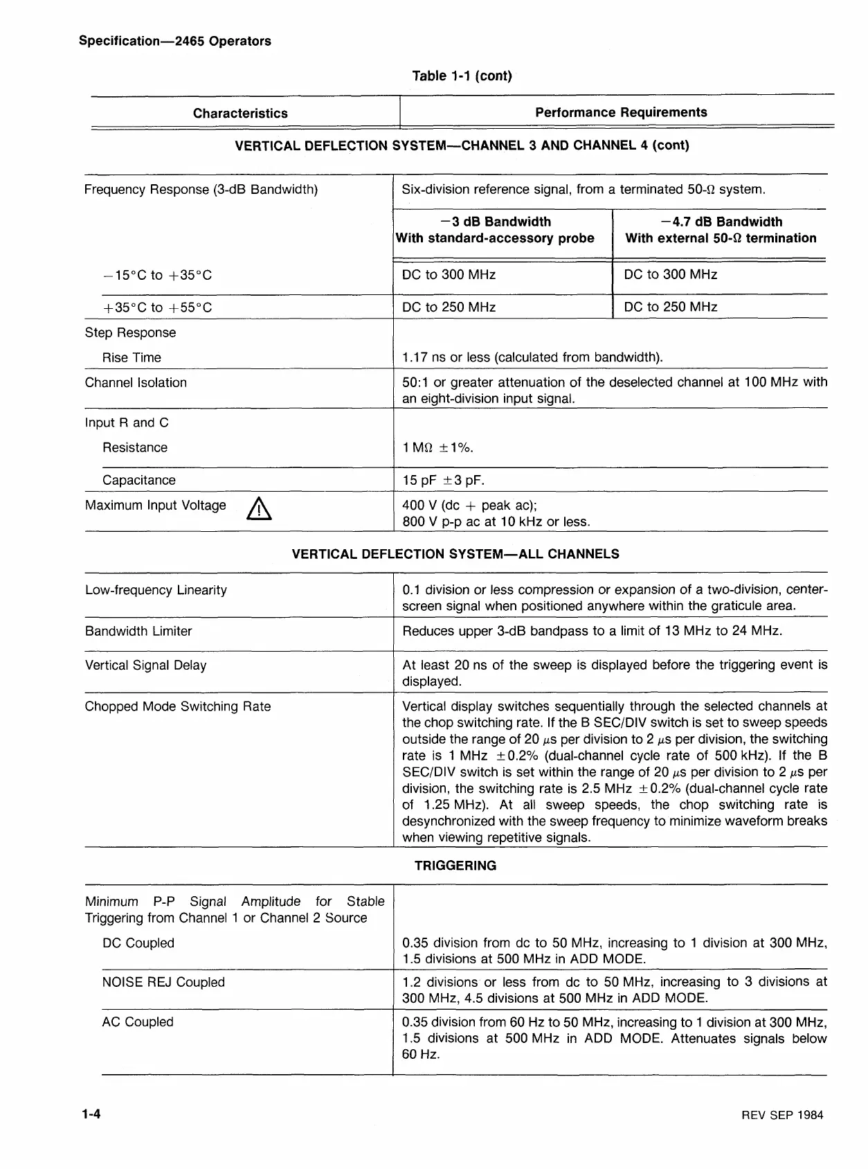
VERTICAL DEFLECTION SYSTEM-CHANNEL
3
AND CHANNEL 4 (cont)
Characteristics
Frequency Response (3-dB Bandwidth)
-15°C to +35"C
Performance Requirements
Step Response
Rise Time
Channel Isolation
lnput R and
C
Resistance
Capacitance
Maximum lnput Voltage
A
Six-division reference signal, from a terminated 504 system.
1.17 ns or less (calculated from bandwidth).
-3
dB Bandwidth
Nith standard-accessory probe
DC to 300 MHz
DC to 250 MHz
50:1 or greater attenuation of the deselected channel at 100 MHz with
-4.7 dB Bandwidth
With external
50-0
termination
DC to 300 MHz
DC to 250 MHz
an eight-division input signal.
400 V (dc
+
peak ac);
800 V
D-D
ac at 10 kHz or less.
VERTICAL DEFLECTION SYSTEM-ALL CHANNELS
Vertical Signal Delay
Low-frequency Linearity
Bandwidth Limiter
At least 20 ns of the sweep is displayed before the triggering event is
displayed.
0.1 division or less compression or expansion of a two-division, center-
screen signal when positioned anywhere within the graticule area.
Reduces upper 3-dB
bandpass to a limit of 13 MHz to 24 MHz.
Chopped Mode Switching Rate
Vertical display switches sequentially through the selected channels at
the chop switching rate. If the B SECIDIV switch is set to sweep speeds
outside the range of 20
ps per division to
2
ps per division, the switching
rate is 1 MHz +0.2% (dual-channel cycle rate of 500 kHz). If the
B
SECIDIV switch is set within the range of 20 ps per division to 2 ps per
division, the switching rate is 2.5 MHz +0.2% (dual-channel cycle rate
of 1.25 MHz). At all sweep speeds, the chop switching rate is
desynchronized with the sweep frequency to minimize waveform breaks
when viewing repetitive signals.
TRIGGERING
-
-
Minimum P-P Signal Amplitude for Stable
Triggering from Channel 1 or Channel 2 Source
DC Coupled
0.35 division from dc to 50 MHz, increasing to 1 division at 300 MHz,
1.5 divisions at 500 MHz in ADD MODE.
NOISE REJ Coupled
1.2 divisions or less from dc to 50 MHz, increasing to 3 divisions at
300 MHz, 4.5 divisions at 500 MHz in ADD MODE.
AC Coupled 0.35 division from 60 Hz to 50 MHz, increasing to 1 division at 300 MHz,
1.5 divisions at 500 MHz in ADD MODE. Attenuates signals below
60 Hz.
REV
SEP 1984

 Loading...


