Operator's Checks and Adjustments-2465 Operators
3.
Connect the Channel 1 probe (using the probe hook
tip) to the oscilloscope CALIBRATOR output.
4.
Set triggering controls for
a
stable display. The dis-
play should be five cycles of the CALIBRATOR square-
wave signal, with an amplitude of four divisions. Center the
display on the screen.
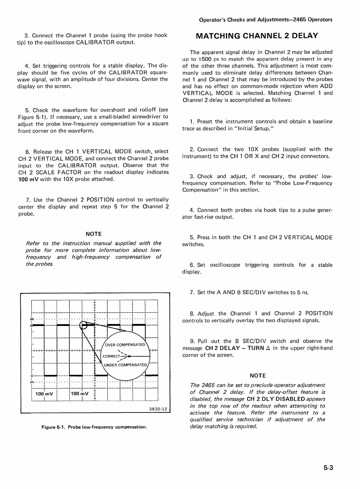
5. Check the waveform for overshoot and rolloff (see
Figure 5-1). If necessary, use
a
small-bladed screwdriver to
adjust the probe low-frequency compensation for
a
square
front corner on the waveform.
6.
Release the CH
1
VERTICAL MODE switch, select
CH
2
VERTICAL MODE, and connect the Channel
2
probe
input to the CALIBRATOR output. Observe that the
CH
2
SCALE FACTOR on the readout display indicates
100
mV
with the 10X probe attached.
7.
Use the Channel
2
POSITION control to vertically
center the display and repeat step 5 for the Channel
2
probe.
NOTE
Refer to the instruction manual supplied with the
probe for more complete information about low-
frequency and high-frequency compensation of
the probes.
Figure
5-1.
Probe low-frequency compensation.
MATCHING CHANNEL
2
DELAY
The apparent signal delay in Channel
2
may be adjusted
up to +500 ps to match the apparent delay present in any
of the other three channels. This adjustment
is
most com-
monly used to eliminate delay differences between Chan-
nel 1 and Channel
2
that may be introduced by the probes
and has no effect on common-mode rejection when ADD
VERTICAL MODE
is
selected. Matching Channel
1
and
Channel
2
delay
is
accomplished
as
follows:
1.
Preset the instrument controls and obtain
a
baseline
trace
as
described in "Initial Setup."
2.
Connect the two 10X probes (supplied with the
instrument) to the CH
1
OR
X
and CH
2
input connectors.
3.
Check and adjust, if necessary, the probes' low-
frequency compensation. Refer to "Probe Low-Frequency
Compensation" in this section.
4.
Connect both probes via hook tips to
a
pulse gener-
ator fast-rise output.
5.
Press in both the CH 1 and CH
2
VERTICAL MODE
switches.
6.
Set oscilloscope triggering controls for
a
stable
display.
7.
Set the A AND B SECIDIV switches to 5 ns.
8.
Adjust the Channel 1 and Channel
2
POSITION
controls to vertically overlay the two displayed signals.
9.
Pull out the B SECIDIV switch and observe the
message
CH 2 DELAY
-
TURN
A
in the upper right-hand
corner of the screen.
NOTE
The
2465
can be set to preclude operator adjustment
of Channel
2
delay. If the delay-offset feature is
disabled, the message
CH 2 DLY DISABLED
appears
in the top row of the readout when attempting to
activate the feature. Refer the instrument to a
qualified service technician if adjustment of the
delay matching is required.

 Loading...


