Theory
of
Operation-314 Service
V
AR
EXT HORlZ
1-q
R385B
1
EXT
\
SWEEP
LOGIC
U340
Q532,
0540
MILLER
6
INTEGRATOR
I
I
I
+
HORlZ
SIGNAL
(TRIG,
i
---------
--------
I-]
HORIZONTAL
R370 POSITIONING
-
- -
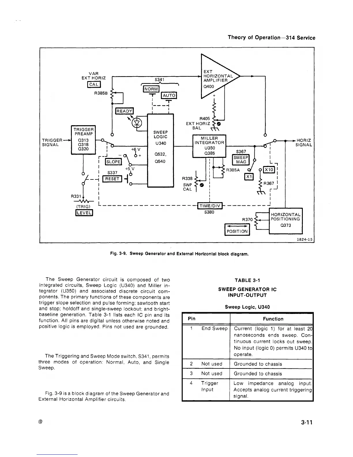
Fig.
3-9.
Sweep Generator and External Horizontal block diagram.
The Sweep Generator circuit is composed of two
integrated circuits, Sweep Logic (U340) and Miller in-
tegrator (U350) and associated discrete circuit com-
ponents. The primary functions of these components are
trigger slope selection and pulse forming; sawtooth start
and stop;
holdoff and single-sweep lockout; and bright-
baseline generation. Table 3-1 lists each
IC pin and its
function. All pins are digital unless otherwise noted and
positive logic is employed. Pins not used are grounded.
The Triggering and Sweep Mode switch, S341, permits
three modes of operation: Normal, Auto, and Single
Sweep.
Fig. 3-9 is a block diagram of the Sweep Generator and
External Horizontal Amplifier circuits.
TABLE
3-1
SWEEP GENERATOR IC
INPUT-OUTPUT
Sweep Logic, U340
1
2
Not used
I
Grounded to chassis
I
Pin
1
End Sweep
1
;
;;;c~~?d
Grounded to chassis
Low impedance analog input.
Input Accepts analog current triggering
signal.
Function
Current (logic 1) for at least
2(
nanoseconds ends sweep. Con
tinuous current locks out sweep
No input (logic 0) permits U340
tc
operate.
 Loading...


