Theory of Operation-314 Service
TABLE
3-1
(cont)
TABLE
3-1
(cont)
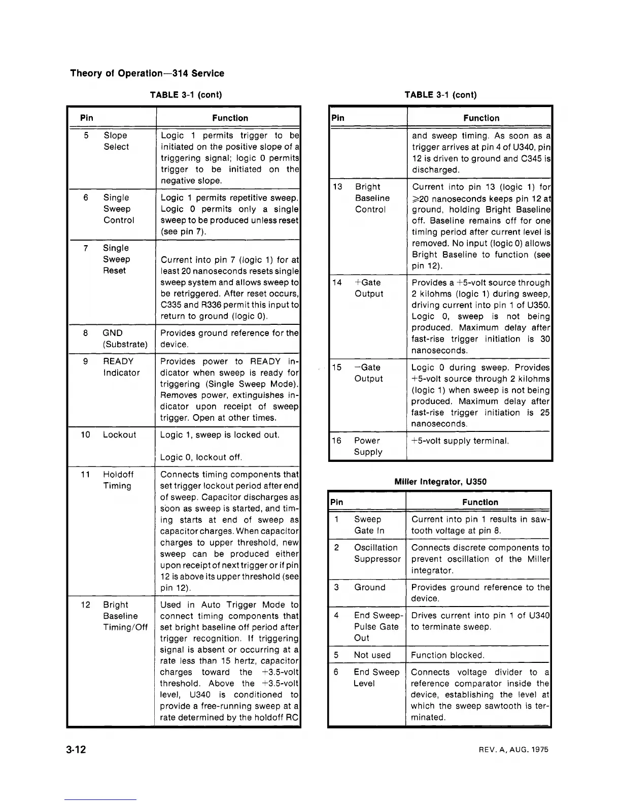
Function
Logic 1 permits trigger to b~
initiated on the positive slope of
triggering signal; logic 0 permit
trigger to be initiated on th~
negative slope.
Logic 1 permits repetitive sweep
Logic
0
permits only a singlc
sweep to be produced unless rese
(see pin
7).
Current into pin
7
(logic 1) for a
least 20 nanoseconds resets sing11
sweep system and allows sweep tc
be retriggered. After reset occurs
C335 and R336 permit this input tc
return to ground (logic 0).
Provides ground reference for thc
device.
Provides power to READY in
dicator when sweep is ready fo
triggering (Single Sweep Mode)
Removes power, extinguishes in
dicator upon receipt of
sweel
trigger. Open at other times.
Logic 1, sweep is locked out.
Logic 0, lockout off.
Connects timing components tha
set trigger lockout period after
en(
of sweep. Capacitor discharges a!
soon as sweep is started, and tim
ing starts at end of sweep a:
capacitorcharges. When capacito
charges to upper threshold, nev
sweep can be produced eithe
upon receipt of next trigger or if
pir
12 is above its upper threshold (sec
pin 12).
Used in Auto Trigger Mode tc
connect timing components tha
set bright baseline off period afte
trigger recognition. If triggerin!
signal is absent or occurring at
i
rate less than 15 hertz, capacito
charges toward the +3.5-vol
threshold. Above the +3.5-vol
level, U340 is conditioned tc
provide a free-running sweep at
i
rate determined by the holdoff RC
Pin
13 Bright
Baseline
Control
14 +Gate
Output
15 -Gate
Output
16 Power
Supply
Function
and sweep timing. As soon as a
trigger arrives at pin 4 of U340, pin
12 is driven to ground and C345 is
discharged.
Current into pin 13 (logic
1)
for1
220 nanoseconds keeps pin 12 at
ground, holding Bright Baseline
I
off. Baseline remains off for one1
timing period after current level is
removed. No input (logic
0)
allows
Bright Baseline to function (see
pin 12).
Provides a +5-volt source throughl
2
kilohms (logic
1)
during sweep,l
driving current into pin 1 of ~350.1
Logic 0, sweep is not being
produced. Maximum delay after
fast-rise trigger initiation is 30
nanoseconds.
I
Logic 0 during sweep. provides1
+5-volt source through 2 kilohms
(logic 1) when sweep is not being
produced. Maximum delay after
fast-rise trigger initiation is 25
nanoseconds.
I
+5-volt supply terminal.
I
Miller Integrator,
U350
'in
I
Function
I
2 Oscillation
Suppressor
-
---
-
-
1 Sweep
Gate In
Connects discrete components to
prevent oscillation of the Miller
integrator.
-
Current into pin 1 results in saw-
tooth voltage at pin
8.
I
3 Ground Provides ground reference to the
device.
I
4 End sweep-/ Drives current into pin 1 of ~3401
Pulse Gate to terminate sweep.
7~
6
End Sweep
I
Connects voltage divider to a1
Level reference comparator inside the
device, establishing the level at
which the sweep sawtooth is ter-
minated.
REV.
A,
AUG.
1975
 Loading...


