4-5. OPERATING
CONSIDERATIONS. To
ensure
optimum
measurement
accuracy,
the following
information
should be
considered
before operating
the
oscilloscope.
a.
Signal
Connections.
In general,
probes offer
the most
convenient
means of
connecting an input
signal to
the in-
strument.
They are shielded to
prevent
pickup of
electro-
static
interference.
The 10X probe offers
a high
input
im-
pedance, which
allows the circuit under
test to perform
very close to normal operation
conditions. However, it
also attenuates the input signal
ten times.
(1)
In
high
frequency
applications that require
maxi-
mum
overall bandwidth,
use coaxial cables
terminated at
both
ends
in
their
characteristic impedance.
For
further
information, refer
to
the
paragraph on Coaxial
Cables
below.
(2)
High
level, low frequency signals may be directly
connected
to the input connectors with short, unshielded
leads. This
coupling method works best for signals below
about one kilohertz
and deflection factors above one volt/
division. When this method
is used, establish
a
common
ground between
the instrument and
the equipment under
test.
To
avoid errors
in the display, keep the
leads away
from
any
source
of
interference. If interference
is exces-
sive
with
unshielded
leads, use a
coaxial
cable
or a probe.
b.
Loading Effect
of Input
Connections. As nearly
as
possible, simulate
actual operating
conditions in the equip-
ment under test.
Otherwise, the equipment
under test may
not produce
a
normal
signal. Because of their
high input
impedance,
the supplied
probes offer the least
circuit
loading. When
the signal is directly
coupled
to the input
of
this instrument,
the input impedance
is about one
megohm
paralleled
by about
20
picofarads.
When the
signal is coupled
to the input through
a
coaxial
cable, the
effective input
capacitance
depends upon
the type and
length
of cable
used.
For
information
on obtaining
maxi-
mum
frequency
response with
coaxial cables,
refer
to
the
paragraph
on
Coaxial
Cables below.
c. Coaxial
Cables. Cables
used
to
connect
signals
to the
input
connectors
have
a large effect
on the
accuracy of
a
displayed
high
frequency
waveform.
(1
)
To maintain
the high
frequency
characteristics
of
an applied signal, high quality,
low loss
coaxial
cable
should be used.
Also,
the cable should
be terminated at
both ends in its characteristic
impedance. If- it is
necessary
to use cables
with differing
characteristic impednaces,
use
suitable
impedance
matching
devices.
AIRFORCE
T033A1-13-496-1
NAVELEX 0969-LP-170-0010
Operation Instructions
(2)
To
maintain
fast rise
time pulse characteristics,
use the
shortest length of coaxial
cable possible.
Also, ob-
serve the cable
criteria for high
frequency
characteristics
in
(1)
above.
d.
Grounding.
Reliable signal measurements cannot
be
made unless both the
instrument and
equipment
under test
are connected
together by
a
common
reference
(ground)
lead in
addition
to
the signal
lead
or
probe. Although
the
three-wire
ac
power cord
provides
a
common connection
with used with
equipment with similar power
cords, the
ground
loop
produced may
make accurate measurements
impossible. The short
ground lead connected to the probes
provide the best signal ground. On coaxial cables, the shield
provides
a
common
ground
when
connected
between two
coaxial connectors (or with
suitable
adapters to provide
a
common ground).
When using unshielded signal
leads,
a
common ground lead should
be
connected from the chassis
of the instrument
(rear panel Ground Binding
Post)
to
the
chassis of
the equipment under test.
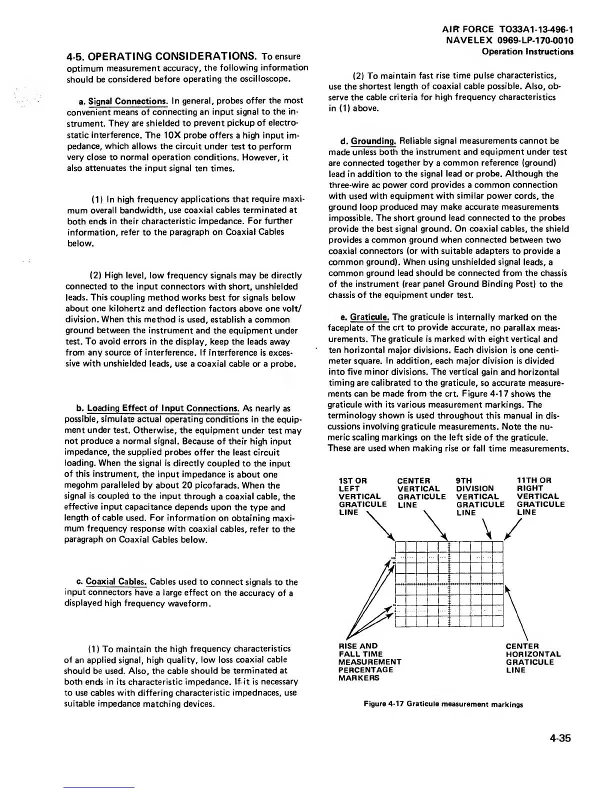
e.
Graticule. The graticule is internally marked
on the
faceplate of the
crt to
provide
accurate,
no
parallax
meas-
urements. The graticule
is
marked
with eight vertical and
ten horizontal major divisions. Each
division
is
one centi-
meter square. In
addition,
each
major division is
divided
into five minor
divisions.
The
vertical gain and
horizontal
timing are calibrated
to
the graticule,
so accurate measure-
ments can be made from the crt. Figure
4-1
7
shows the
graticule with its various
measurement markings.
The
terminology
shown is used throughout this
manual in dis-
cussions involving graticule measurements.
Note the nu-
meric scaling markings
on the left side of the graticule.
These are used when making rise or fall
time measurements.
1ST
OR CENTER 9TH
11TH OR
LEFT VERTICAL DIVISION
RIGHT
VERTICAL
GRATICULE VERTICAL
VERTICAL
GRATICULE
LINE
GRATICULE
GRATICULE
FALL TIME
MEASUREMENT
PERCENTAGE
MARKERS
HORIZONTAL
GRATICULE
LINE
Figure
4-17
Graticule
measurement
markings
4-35
 Loading...


