AIR FORCE T033A1-13-496-1
NAVELEX
0969-LP-170-0010
Maintenance
Instructions
Rise Time.
Connect the equipment
as
shown in step
7.a.
Preset controls as listed in step 1
.a.,
then reset
as
follows:
A
AND BTIME/DIV
,05ms
CH 1 VOLTS/D IV
20
m
Set
calibration generator for
a 5
division display at 1
megahertz.
Adjust
vertical POSITION
to place display
between the
0
and 100%
markers on the graticule.
Set X10 MAG to the In position (on).
Normal Indication
Measure the time duration of the positive going portion
of
the
display be-
tween 10 and 90% markers on the graticule
3.5
nanoseconds
(0.7
division)
or
less.
Change the calibration generator
output
from CH 1 to
CH
2.
Set controls as
follows;
CH 2 VOLTS/DIV
VERT MODE
X10 MAG
20 m
CH 2
Out
(off)
Repeat steps 8.c. through 8.f.
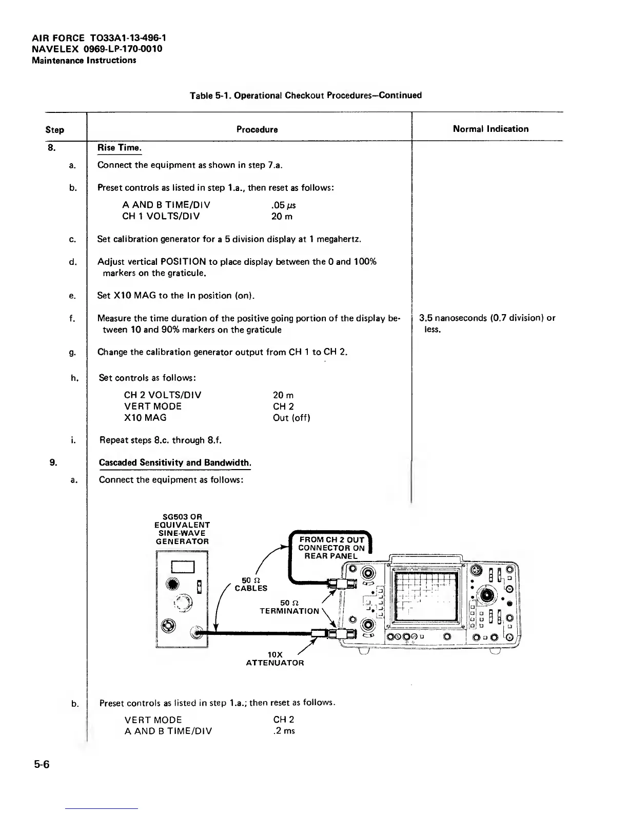
Cascaded
Sensitivity
and Bandwidth.
Connect the equipment
as
follows:
SG503 OR
EQUIVALENT
SINE-WAVE
GENERATOR
50 n
CABLES
FROM
CH 2
OUT
CONNECTOR
ON
REAR
PANEL
50 n
TERMINATION'
10X
ATTENUATOR
2Sli,0
Qj
“
r,
Preset controls
as listed in
step
l.a.;
then
reset as
follows.
VERT MODE
CH 2
A
AND B
TIME/DIV
.2 ms
 Loading...


