AIR FORCE
T033A1
-13-496-1
NAVELEX 0969-LP-170-0010
Operation Instructions
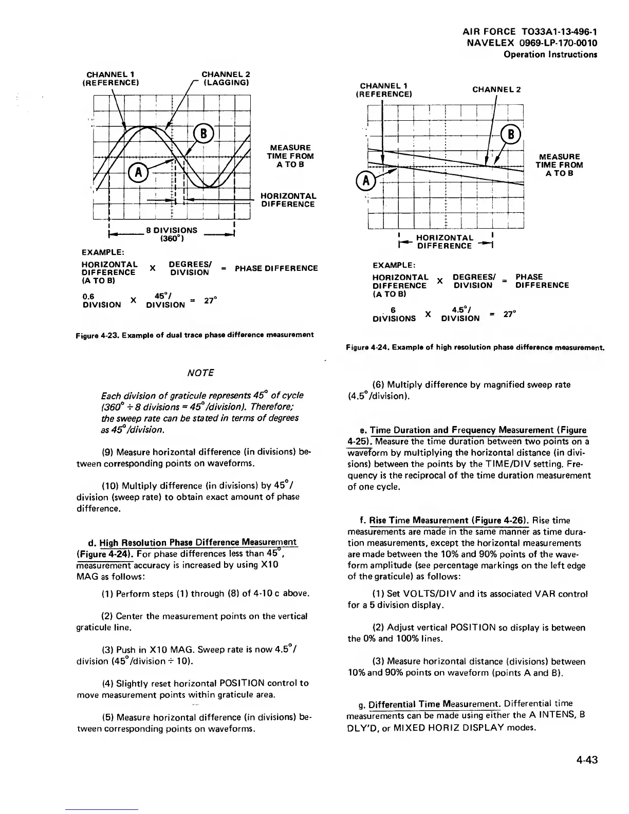
CHANNEL 1
CHANNEL
2
MEASURE
TIME FROM
A
TOR
HORIZONTAL
DIFFERENCE
EXAMPLE:
HORIZONTAL
^
DEGREES/
DIFFERENCE
^
DIVISION
(A TO
B)
PHASE
DIFFERENCE
0.6
X
=
27
DIVISION DIVISION
MEASURE
TIME
FROM
ATOB
EXAMPLE;
HORIZONTAL
^
DEGREES/
_
PHASE
DIFFERENCE
DIVISION
DIFFERENCE
(A
TO B)
6 „
4.5°/
^
„o
DIVISIONS
DIVISION
Figure
4-23. Example
of dual
trace phase
difference
measurement
Figure
4-24.
Example
of
high
resolution
phase difference
measurement.
NOTE
Each
division
of graticule
represents
45°
of cycle
(360°
-r
8
divisions
= 45°
/division).
Therefore;
the
sweep rate
can be stated
in terms of
degrees
as
45°
/division.
(9)
Measure
horizontal difference
(in divisions)
be-
tween
corresponding points
on waveforms.
(10)
Multiply
difference (in
divisions)
by
45°/
division (sweep
rate)
to
obtain
exact amount of
phase
difference.
d.
High
Resolution
Phase Difference
Measurement
(Figure
4-24). For
phase differences
less
than
45
,
measurement accuracy
is
increased by
using XI
0
MAG
as
follows:
(1
)
Perform steps
(1
)
through
(8)
of
4-10
c
above.
(2)
Center the measurement
points on the vertical
graticule line.
(3)
Push
in XI
0
MAG.
Sweep
rate is now
4.5°/
division
(45°
/division
-i-
10).
(4)
Slightly reset
horizontal
POSITION
control
to
move measurement
points within
graticule area.
(5)
Measure horizontal difference
(in
divisions) be-
tween corresponding
points on waveforms.
(6)
Multiply difference
by
magnified sweep rate
(4.5°
/division).
e.
Time Duration and
Frequency Measurement (Figure
4-25).
Measure
the time duration between two points
on a
waveform by
multiplying the horizontal distance (in
divi-
sions) between
the points
by
the TIME/DIV setting. Fre-
quency
is the reciprocal of the time duration measurement
of one cycle.
f.
Rise Time
Measurement
(Figure
4-26).
Rise time
measurements are made in the same manner
as time dura-
tion measurements, except the horizontal measurements
are made between
the 10% and
90%
points of the wave-
form amplitude (see
percentage markings on the left
edge
of the
graticule) as follows:
(1)
Set VOLTS/DIV and its associated
VAR control
for
a 5
division display.
(2)
Adjust vertical POSITION
so
display
is
between
the 0%
and
100% lines.
(3)
Measure horizontal
distance (divisions) between
10% and
90%
points on waveform
(points
A
and
B).
g.
Differential
Time
Measurement.
Differential
time
measurements
can be
made using
either the A
INTENS, B
DLY’D, or
MIXED
HORIZ
DISPLAY
modes.
4-43
 Loading...


