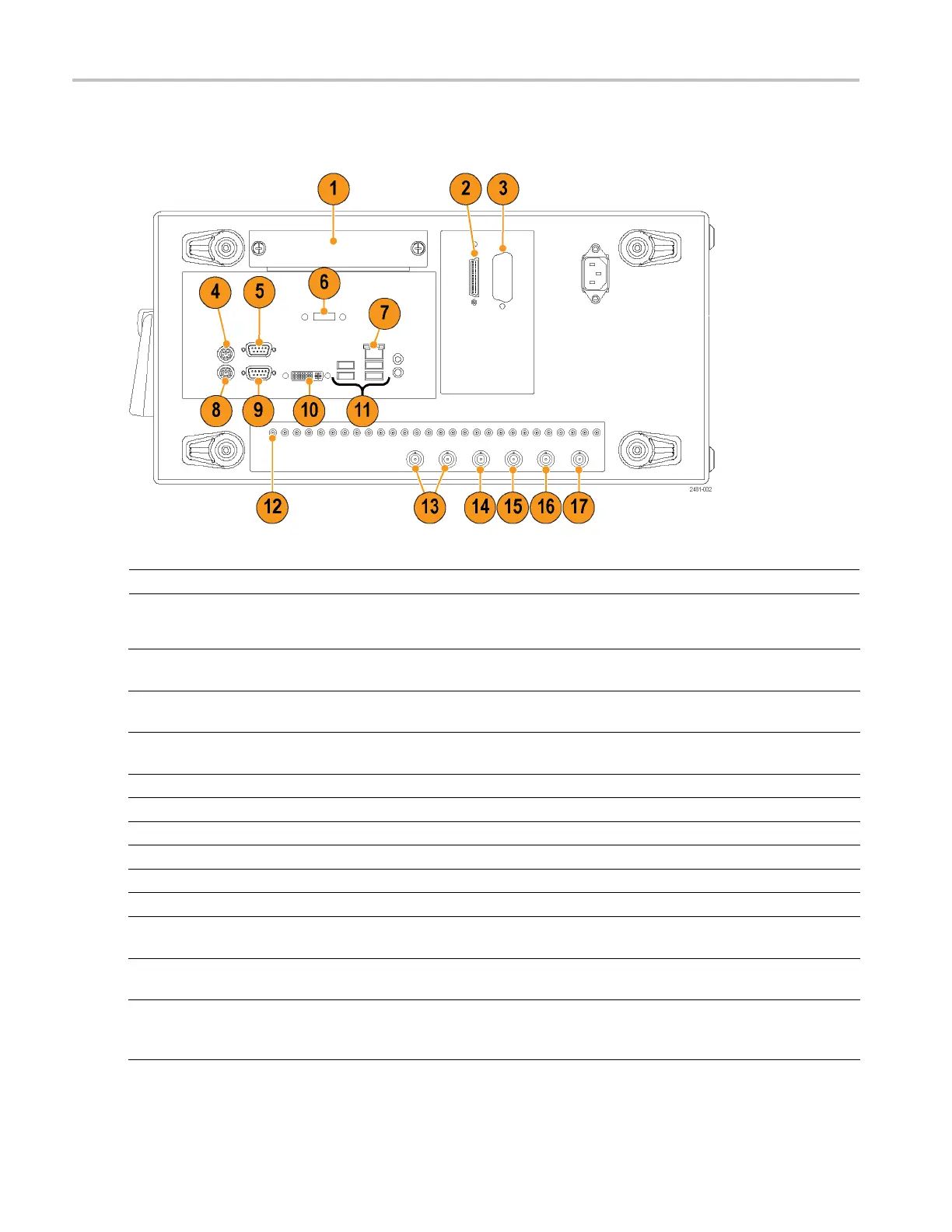
Rear Panel (AWG5
000C Series)
Rear Panel (AW
G5000C Series)
NOTE. AWG5000B series have a similar connectors in different locations.
Connector Description
1. Remova
ble HDD
Removable hard disk drive to secure data. If you remove the HDD, user information
such as setup files or w aveform data does not remain within the instrument.
2. TekLink
Use the TekLink connector for data import or connecting the Option 09 TTL Event to
TekLi
nk LVDS Connector Adapter box.
3. GPIB Use t
he GPIB connector to connect the instrument to a GPIB controller for GPIB
operation.
4. PS-2 Mouse c onnector Use the PS-2 connector to connect a mouse to the instrument.
5. COM2 Use the COM2 serial port to connect to other devices through the serial port.
6. eSATA port Use the eSATA port to connect external SATA devices to the instrument.
7. LA
N
Us
e the RJ-45 connector to connect the instrument to a network.
8
.
P
S-2 Keyboard connector
U
se the PS-2 connector to connect a PS-2 keyboard to the instrument.
9
.
C
OM1
U
se the COM1 serial port to connect to other devices through the serial port.
10. Video
Use the DVI-I Video port to connect a monitor for extended desktop operation. To
connect a VGA monitor to the DVI-I connector, use a VGA-to-DVI adapter.
11. USB Use the USB connectors to connect a US B mouse, keyboard, or other USB device
to the instrument.
12. Digital Data Out Use these connectors to output digital data. To enable digital data output, O ption
03 must be installed in the AWG5002C, AWG5012C, AWG5002B, or AWG5012B.
Connector Type: SMB
16 AWG5000 and AWG7000 Series Quick Start User Manual

 Loading...


