Check aux trigger out
Equipment required Prerequisites
One precision 50 Ω coaxial cable (Item 4)
One 2X attenuator (Item 33)
(See Prerequisites on page 116.) Also, the
instrument must have passed the DC Voltage
Measurement Accuracy. (See Signal acquisition
system checks on page 176.)
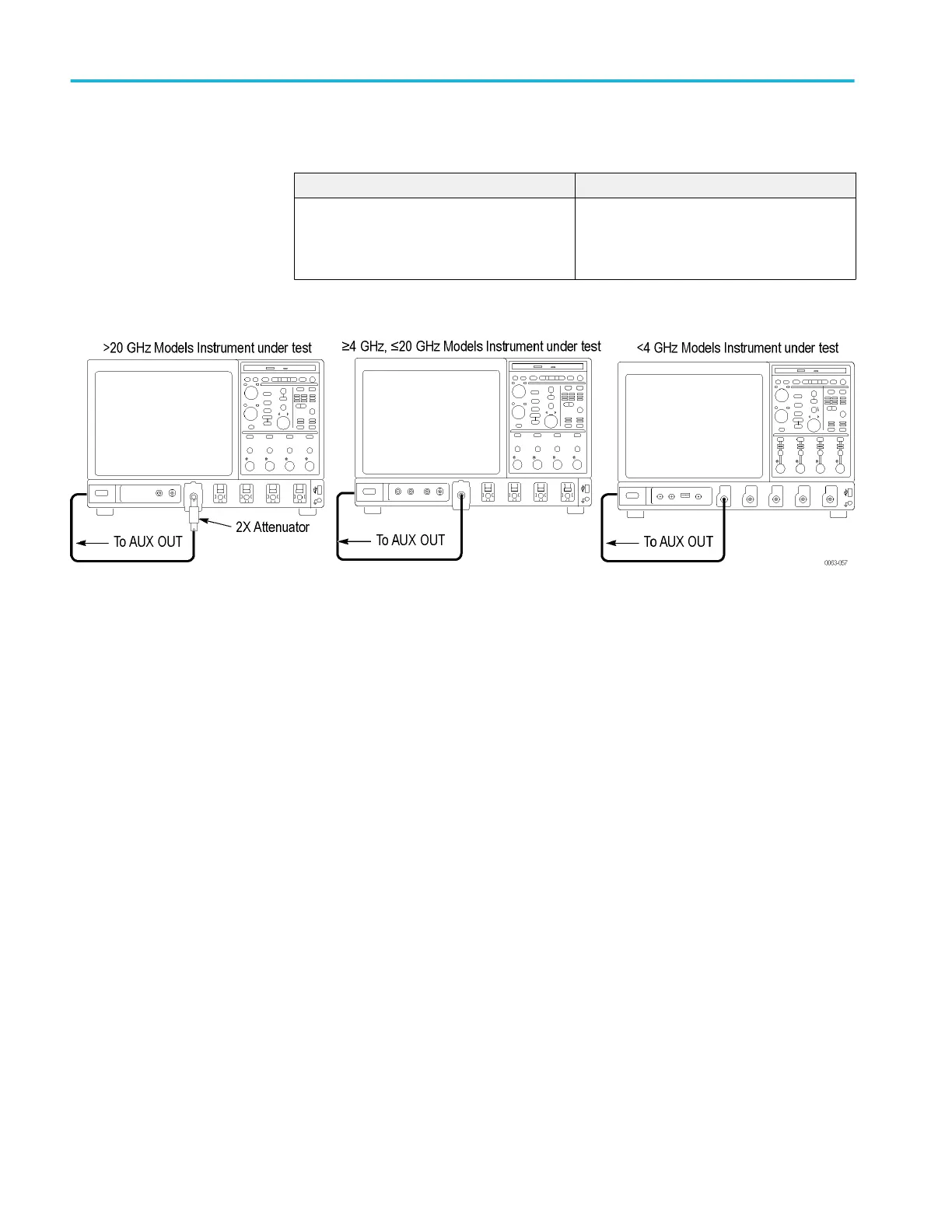
1. Install the test hookup and preset the instrument controls:
Figure 35: Aux Trigger Out test hookup
a. Hook up test-signal source: Connect Aux Out to Ch 1 through a 50 Ω
precision cable and an adapter. (See Figure 35: Aux Trigger Out test
hookup.)
b. Initialize the instrument: Press the Default Setup button.
c. Modify the initialized front-panel control settings:
■
Press the Vertical Ch 1 button to toggle it off.
■
Set the Horizontal Scale to 200 μs.
■
From the button bar, touch Horiz/Acq and select the Acquisition
tab.
■
Touch Average and set the number of averages to 64.
■
Touch the X (close) button.
2. Confirm Aux Out is within limits for logic levels:
a. Display the test signal:
■
Press the Vertical Ch 1 button to display that channel.
■
< 4 GHz models: Touch Vertical, select Vertical Setup, and then
touch Termination 50 Ω.
Performance verification (MSO/DPO70000C, MSO/DPO70000DX, and DPO7000C series)
266 MSO70000C/DX, DPO70000C/DX, DPO7000C, MSO5000/B, DPO5000/B Series
 Loading...


