Check input impedance (Resistance)
This test checks the Input Impedance.
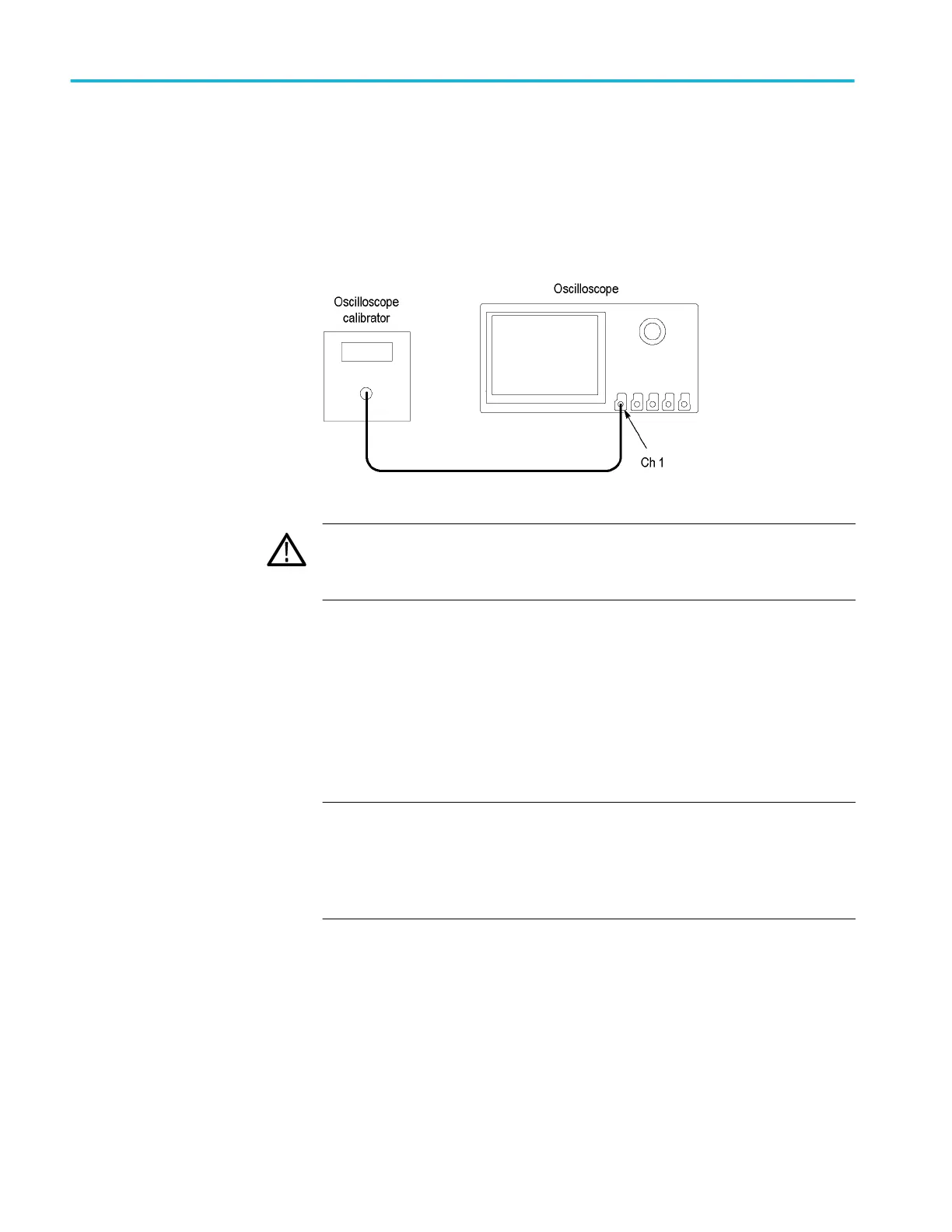
1. Connect the output of the oscilloscope calibrator (for example, Fluke 9500)
to the oscilloscope channel 1 input, as shown in the following illustration.
WARNING. The generator is capable of providing dangerous voltages. Be
sure to set the generator to off or 0 volts before connecting, disconnecting,
and/or moving the test hookup during the performance of this procedure.
2.
Push the front-panel Default Setup button.
3. Set the impedance to 1 MΩ as follows:
a. Set the calibrator impedance to 1 MΩ.
b. Push the front-panel Vertical V menu button.
c. Set the Termination to 1 MΩ.
4. Set the Vertical Scale to 10 mV/div.
NOTE. Impedance measuring equipment that produce a voltage across the
channel that exceeds the measurement range of the instrument may report
erroneous impedance results. A measurement voltage exceeds the
measurement range of the instrument when the resulting trace is not visible
on the graticule because of the measurement voltage amplitude.
5. Use the calibrator to measure the input impedance of the oscilloscope and
enter the value in the test record.
6. Repeat steps 4 and 5 for all vertical scale settings in the test record.
7. Repeat the tests at 250 kΩ as follows:
a. Set the calibrator impedance to 1 MΩ.
b. In the toolbar, click the Utilities menu and select Instrument
Diagnostics.
c. Click the on-screen Manual Product Verification button.
Performance verification (MSO/DPO5000/B series)
318 MSO70000C/DX, DPO70000C/DX, DPO7000C, MSO5000/B, DPO5000/B Series
 Loading...


