Pinpoint Trigge
rs
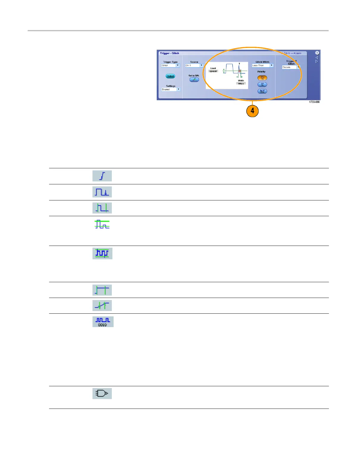
4. Complete the trigger setup using the
controls displayed for the trigger type.
The controls t
o set up the trigger vary
depending on the trigger type.
Pinpoint T
rigger Selections
Trigger Type Trigger Conditions
Edge
Trigger on a rising or falling edge, as defined by the slope control. Coupling choices
are DC, AC, LF Reject, HF Reject, and Noise Reject.
Glitch
Trigger on a pulse narrower (or wider) than the specified width or ignore glitches
narrower (or wider) than the specified width.
Width
Trigger on pulses that are inside or outside a specified time range. Can trigger
on positive or negative pulses.
Runt
Trigger on a pulse amplitude that crosses one threshold but fails to cross a second
threshold before recrossing the first. Can detect positive or negative runts, or only
those wider than a specified width. These pulses can also be qualified by the logical
state of other channels.
Window
Trigger when the input signal rises above an upper threshold level or falls below a
lower threshold level. Trigger the instrument as the s ignal is entering or leaving the
threshold window. Qualify the trigger ev ent in terms of time by using the Trigger
When Wider option, or by the logical state of other channels using the Trigger When
Logic option.
Timeout
Trigger when no pulse is detected within a specified time.
Transition
Trigger on pulse edges that traverse between two thresholds at faster or slower rates
than the specified time. The pulse edges can be positive or negative.
Serial Trigger on 64-bit serial pattern at data rates up to 1.25 Gb/s (<4 GHz models) and
40-bit serial patterns up to 3.125 Gb/s (≥4 GHz models only) or 5 Gb/s (≥4GHzB
models). Lock on a pseudo-random bit sequence. Requires Option PTM or PTH.
This mode includes clock recovery. Push the Push Set 50% knob to reinitialize
clock recovery.
Pattern Lock automatically fi nds and locks on a long repeating pseudo-random bit
sequence (PRBS). This lock means that the instrument knows the bit length of the
pseudo-random bit sequence and can predict when the cycle repeats. Pattern Lock
enables the instrument to take samples at specific locations in a data pattern with
outstanding timebase accuracy.
Pattern
Trigger when logic inputs cause the selected function to become True o r False. You
can also specify that the logic conditions must be satisfied for a specific amount of
time before triggering.
50 DPO7000 Series and DPO /DS A70000/B Series Quick Start User Manual
 Loading...


