Specifications
The duty cycle o
f the EXT_IQ_DAV signal varies from 100% at the widest SPAN
values to a very small percentage at the narrowest SPAN values. (See Table 68.)
At a SPAN of 100 Hz, the duty cycle will be 0.00038%; here, the EXT_IQ_DAV
signal is active (high) for 20 ns, and then inactive (low) for ≈5.28 ms.
The length of time that the EXT_IQ_DAV signal is inactive can be used to
determine if the RSA5100B is performing an alignment or a control change. If
the EXT_IQ_DAV signal is inactive for longer than 10 ms, then the RSA5100B
digital I/Q output data stream has been interrupted.
External equipment used to detect the occurrence of a data interruption can
monitor the state of the EXT_IQ_DAV signal. If the EXT_IQ_DAV signal is
inactive
for 10 ms or more, an alignment or control change has occurred. The
duration of the data interruption can be determined by measuring the time between
successive EXT_IQ_DAV pulses.
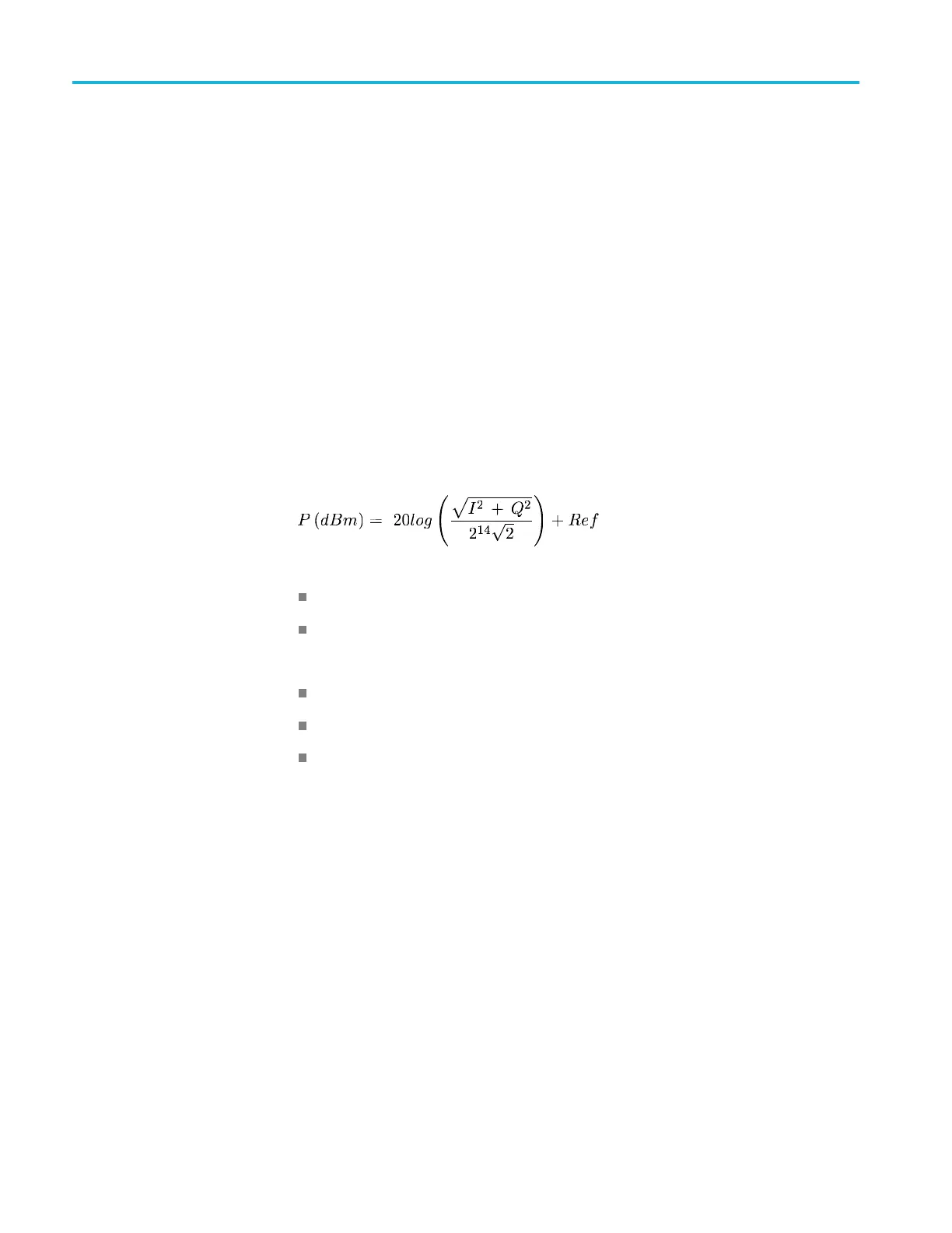
Digital IQ Output Scaling
Output p
ower in dBm for a sinusoidal input
Where:
Where:
I and Q are the digital values at the Digital IQ output port
Ref = Reference Level
Valid for center frequencies that exceed:
Center frequency ≥ 80 MHz for Spans > 40 MHz
Center freq
uency ≥ 30 MHz for Spans > 312.5 kHz and ≤ 40 MHz
Center frequency ≥ 2 MHz for Spans < 312.3 kHz
70 RSA5100B Series Technical Reference
 Loading...


