Performance Verification
Check Reference Output
Power Level
1. Set up the power
meter and sensor.
NOTE. Store the power sensor correction factors in the power meter, if you have
not yet done so.
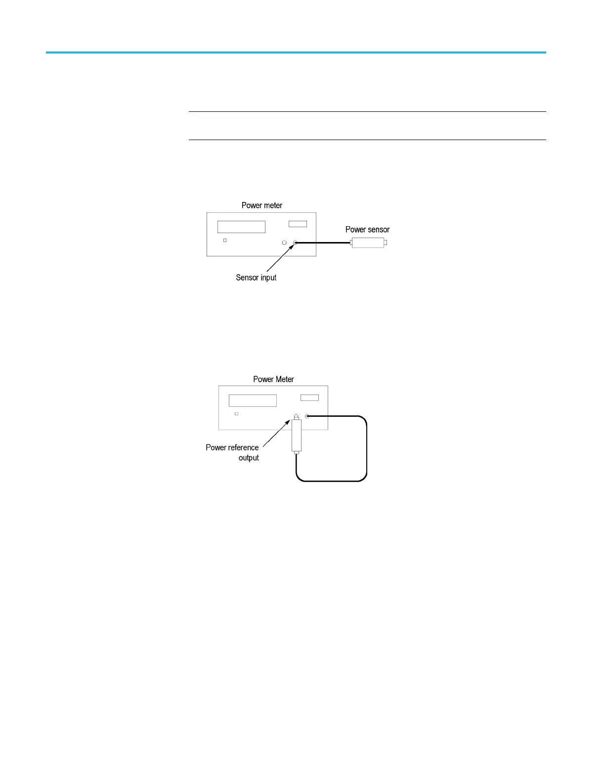
a. Connect the power sensor to the Sensor input on the power meter, as
shown in the following figure.
Figure 4: Power meter setup
b. Press Zero/Cal,andthenpressZERO on the power meter.
c. Connect the RF input of the power sensor to the power meter power
reference output, as shown in the following figure.
Figure 5: Power meter calibration
d. Press CAL to execute the calibration.
e. Disconnect the RF input of the power sensor from the power meter
reference output.
2. Connect the power sensor RF input to the Ref Out connector on the
RSA5100B rear-panel, using the N-female to BNC male adapter (see the
following figure).
3. Press Frequency/Cal Factor, and then set Freq to 10 MHz.
4. Check that the Ref Out signal is >0 dBm. Enter this level in the test record.
76 RSA5100B Series Technical Reference
 Loading...


