Specifications
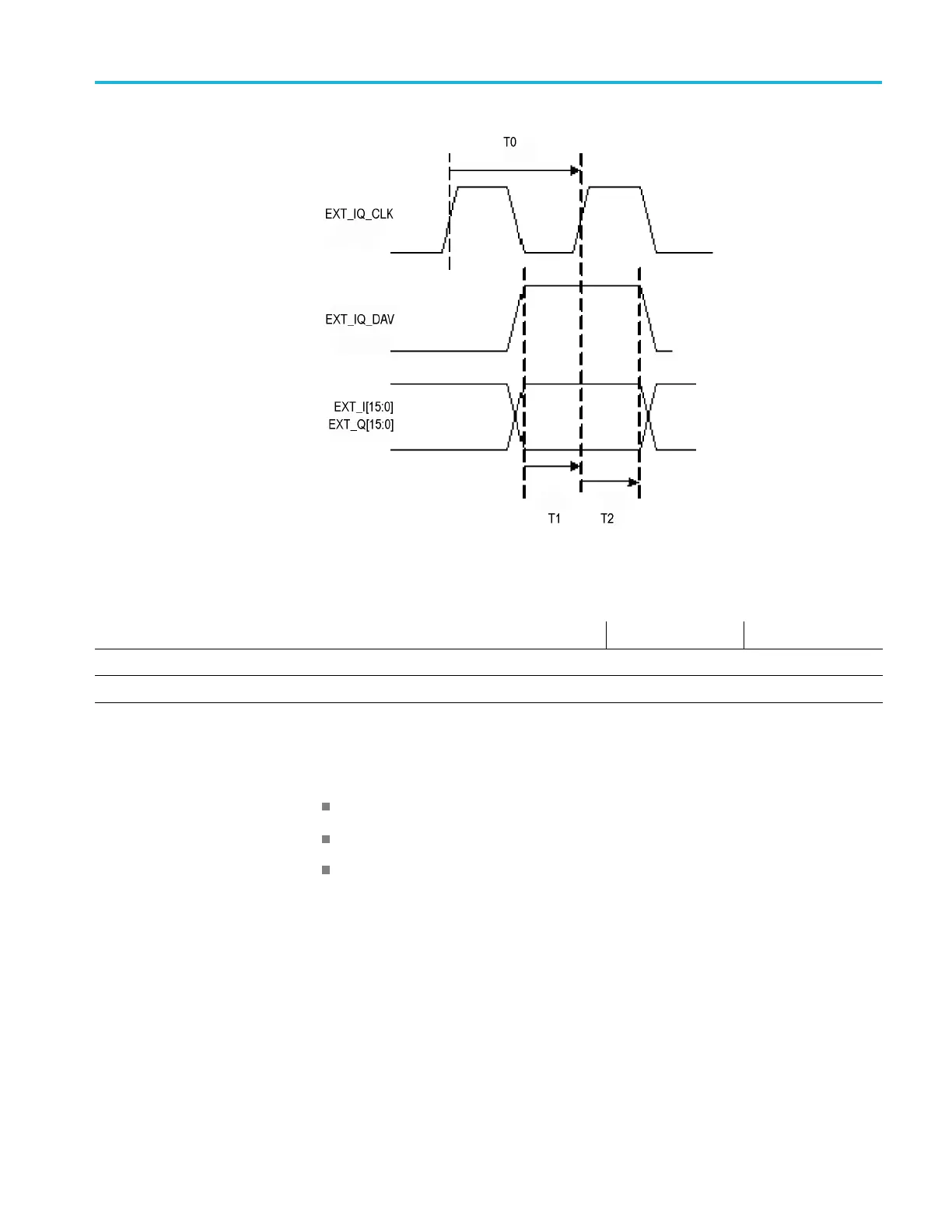
Figure 2: IQ Timing
Table 69: IQ Timing
Real Tim e Span Mode T0 (Clock Period) T1 (Min Setup time) T2 (Min Hold Time)
>40 MHz 16-bit
5ns
1.20 ns 1.23 ns
40 MHz 16-bit 20 ns 8.2 ns 8.4 ns
Possi
ble Interruption
of Data from Digital I/Q
Outputs
There are three conditions during which the RSA5100B will interrupt the flowof
data to the digital I/Q outputs. Those conditions are:
Alignments
Control Changes
Stitched Spectrum Mode
Wh
en any of these conditions are active, the EXT_IQ_DAV signal will be held in
its inactive state. The EXT_IQ_CLK signal will remain active and operate atthe
frequency consistent with the SPAN value selected for the RSA5100B.
The EXT_IQ_DAV signal will remain inactive for the duration of any alignment
or control change. Once the alignment or control change has been completed,the
EXT_IQ_DAV signal becomes active again. While the EXT_IQ_DAV signal is
inactive, the data from the digital I/Q outputs are not valid and should be ignored.
RSA5100B Series Technical Reference 69
 Loading...


