Removal and Installation Procedures
Maintenance
6Ć32
H Front Cover, Trim Ring, Menu Buttons, and Attenuator Panel
%/
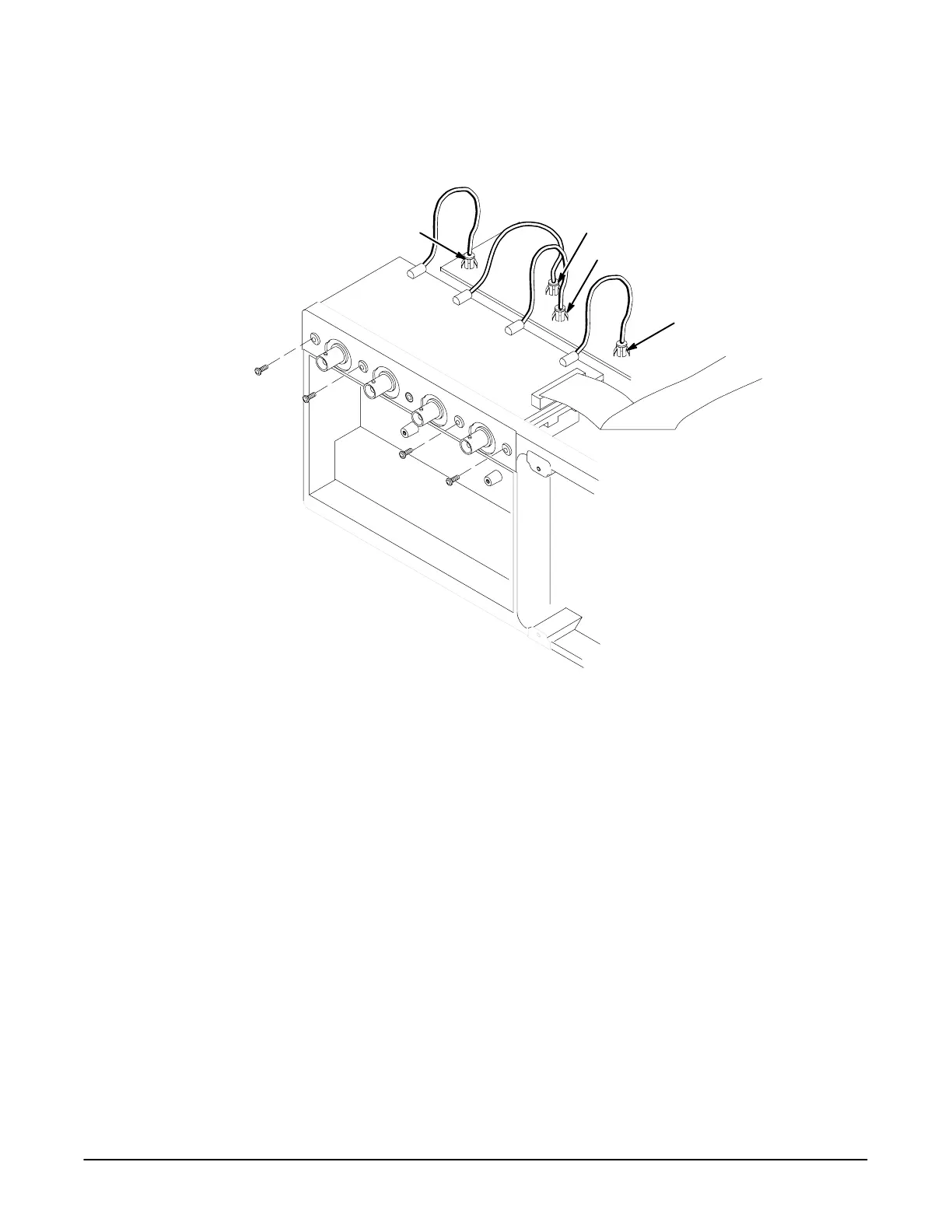
J1100
J1200
J1300
J1400
Figure 6Ć12:ăAttenuator Interconnect Cable Routing and Jack Locations
H Rear Cover and Cabinet % /
Fan
Assemble equipment and locate module to be removed: * #-
'&+&*& +( '. / $&,R (% ("' # $( ( # #
( !$($& &" OuterĆChassis Modules )& / % /
Orient the oscilloscope: ( ( $'!!$'$% '$ (' $(($" ' $+# $# (
+$& ')& # (' !( ' ' # -$)
Disconnect the fan from processor/display board: #%!) ( #' %$+&
! &$"
Remove the fan: "$* ( (+$ '&+' ')&# ( # ($ ( "#
''' # !( ( # +- &$" ( '''
 Loading...


