Troubleshooting
Maintenance
6Ć74
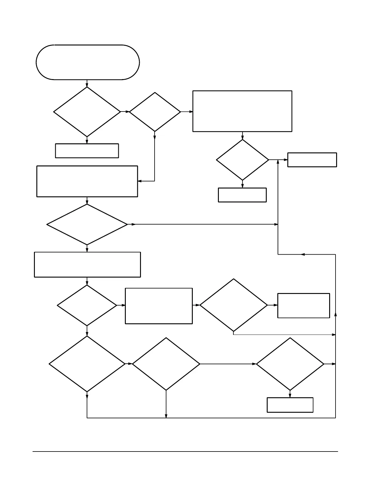
Do all
the channels
display defective
waveforms?
Attach a probe to the PROBE
COMPENSATION signal located on the
front of the oscilloscope. Connect the probe
to a channel's BNC on the front, select the
channel and view the output on the display.
Do this for all the channels.
For all
the channels, is the
signal on the display a
1 kHz ±0.250ĂV
square wave?
Yes
No
No
Yes
The Acquisition/Attenuator
Interface is ok.
Yes
No
Attach the PROBE COMPENSATION signal
to the CH 1 BNC on the front of the
oscilloscope. Remove the coax connector
from J1400 on the A10 Acquisition module.
Probe J700 but DO NOT
REMOVE the cable from the
connector. The voltages will
change if the A10 Acquisition
module is not connected to
the power supply.
Probe
J700 pins 10, 36,
16, and 8. Are these
pins +15ĂV, +5ĂV,
-5.1ĂV, and -15ĂV
respectively?
Perform the Low
Voltage Power Supply
troubleshooting
procedure.
Replace the A15
Attenuator module.
Replace the A10
Acquisition module.
Is a 1 kHz
±0.250ĂV square
wave displayed
now?
Set all the channels to the same vertical
scale and select a channel that works
correctly. Attach the PROBE
COMPENSATION signal to a defective
channel's BNC on the front of the
oscilloscope and swap these two
channels' coaxes to the A10 Acquisition
module.
No
Yes
Replace the A15
Attenuator module.
While
turning the
vertical SCALE knob
again, does J1153
pin 26 swing
between +5 V
and 0 V?
No
Yes
While
turning the vertical
SCALE knob, does
J1153 pin 24 pulse low
swinging between
+5 V and
0 V?
No
Yes
Probe
the detached end
of the coax. Is there a
1ĂkHz ±0.250ĂV square
wave on the
coax?
No
Yes
Power the oscilloscope off and disconnect the
cable attached to J1153 on the A10 Acquisition
module. Power on and probe J1153 pins 14,
16, 18, and 20.
Are these
pins +15ĂV, +5ĂV,
-5.1ĂV, and -15ĂV
respectively?
No
Yes
While
turning the
vertical SCALE
knob, see if J1153 pin 22
pulses low swinging
between +5 V and 0 V.
Does this
occur?
Yes
No
Figure 6Ć39:ă Attenuator/Acquisition Troubleshooting Procedure
 Loading...


