Troubleshooting
TDS 520A, 524A, 540A, & 544A Service Manual
6Ć65
Replace the A10
Acquisition
module.
Perform the A16 Low Voltage
Power Supply Module Isolation
troubleshooting procedure.
Does
the oscilloscope
power on, all the
diagnostics pass, but
sometime later powers
down on its
own?
Yes
No
Yes
No
No
Yes
Press on the principal
power switch on the back
of the oscilloscope.
Can you
hear the fan
whirling?
Press
the ON/STBY
button. Can you
hear the
fan now?
When
the oscilloscope
powers on, do the front
panel lights come on and
then go off up to 60
seconds
later?
Yes
No
Perform the
Processor/Front Panel
troubleshooting
procedure.
Power off and remove the
cover using the Rear Cover
and Cabinet removal
procedure. Check all the
cables coming out of the
Low Voltage Power
Supply. and the cabling
between modules. Be sure
every cable is attached
securely.
Does the
system power
on now?
Yes
Does
the display
seem to be
working
at all?
No
Does
DS1 flash .8,
then display the
sequence of hex
numbers
pausing to
flash .c?
Press S1002 on
the A11 DRAM
Processor/Display
module towards
the back of the
oscilloscope and
cycle power.!
Is
the display
readable and
stable?
Yes
No
No
Yes
Yes
No
Perform the
Display
troubleshooting
procedure.!
There is something
wrong with the
ON/STBY button.
Perform the
Processor/Front
Panel
troubleshooting
procedure.
Yes
No
Power off the
oscilloscope and
remove its cabinet
using the Rear Cover
and Cabinet removal
procedure. On
the A11 DRAM
Processor/Display
module set S1001's
eighth switch to the
open position.
Does DS1
first flash .8, then
display a sequence
of hex numbers from
1-e with no period
preceding
them?
Perform the A16 Low
Voltage Power Supply
Module Isolation
troubleshooting
procedure.
Perform the Module Isolation
troubleshooting procedure.
Does
the oscilloscope
respond correctly
when the front
panel buttons are
pushed?
Yes
No
Perform the
Processor/Front Panel
troubleshooting
procedure.
Does
DS1 flash .8,
then display the
sequence of hex
numbers
pausing to
flash .d?
Replace the A11 DRAM Processor/Display
module.!
Note: The replacement module may not
have the correct firmware loaded. See
6Ć64 for details on firmware updates.
Replace the
A11 DRAM
Processor/Display
module.!
Yes
No
Power
on again and
observe the LED
( DS1). Does it
only display
.8?
Yes
Replace the
A11 DRAM
Processor/Display
module.!
Is
there 5.1ĂV
on J27 pin 17
(see figure
6Ć40)?
Yes
No
Perform the A16 Low
Voltage Power Supply
Module Isolation
troubleshooting procedure.!
No
!Note: Set all the switches on S1001 back to the
closed position and cycle power before performing another procedure.
Did
you find the faulty
module?
Yes
No
Done.
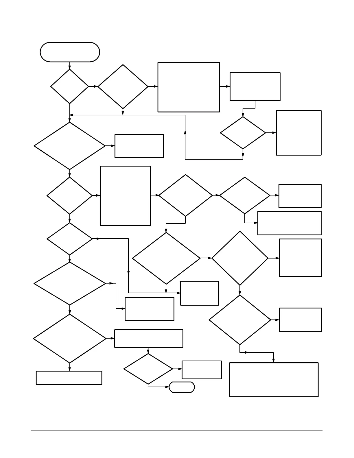
Figure 6Ć30:ăPrimary Troubleshooting Procedure
 Loading...


