Performance Tests
1–68
TDS 500D, TDS 600C, TDS 700D & TDS 714L Performance Verification and Specifications
NOTE. You just checked the trigger sensitivity. If desired, you may repeat steps 1
through 4 for the other channels (CH2, CH3, and CH4).
5. Disconnect the hookup: Disconnect the cable from the channel last tested.
Output Signal Checks
The procedure that follows checks those characteristics of the output signals that
are listed as checked under Warranted Characteristics in Specifications. The
oscilloscope outputs these signals at its front and rear panels.
Equipment
required
Two precision 50 W coaxial cables (Item 5)
One calibration generator (Item 10)
Prerequisites See page 1–17. Also, the oscilloscope must have passed Check DC
Voltage Measurement Accuracy on page 1–38.
See Input Channels versus Model on page 1–2.
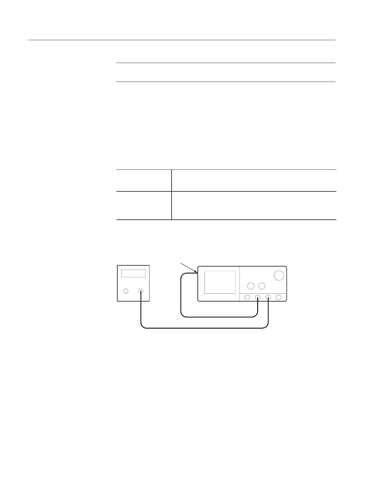
1. Install the test hookup and preset the instrument controls:
50 W coaxial cables
To MAIN
TRIGGER
OUT
Calibration
Generator
Oscilloscope
Figure 1–19: Initial test hookup
a. Hook up test-signal source 1 (See Figure 1–19):
H Connect the standard amplitude output of a calibration generator
through a 50 W precision coaxial cable to CH 3 (AUX1 on some
TDS models).
H Set the output of the calibration generator to 0.500 V.
b. Hook up test-signal source 2: Connect the Main Trigger Out at the rear
panel to CH 2 through a 50 W precision cable.
Check Outputs — CH 3
(AUX 1 on some models)
Main and Delayed Trigger
Artisan Technology Group - Quality Instrumentation ... Guaranteed | (888) 88-SOURCE | www.artisantg.com

 Loading...


