Acquiring and Displaying Waveforms
TDS 500D, TDS 600B, & TDS 700D User Manual
3–65
Table 3–6: DPO XY Format pairs
XY Pair X-Axis source Y-Axis source
Ch 1 and Ch 2 Ch 1 Ch 2
Ch 3 and Ch 4 (Ax1 and Ax2) Ch 3 (Ax1) Ch 4 (Ax2)
Ref 1 and Ref 2 Ref 1 Ref 2
Ref 3 and Ref 4 Ref 3 Ref 4
XYZ format compares the voltage levels of the CH 1 (X) and CH 2 (Y) waveform
records point by point as in XY format. The displayed waveform intensity is
modulated by the CH 3 (Z) waveform record. XYZ format is not triggered. XYZ
format is not available on 2+2 channel oscilloscopes. A –5 division signal
(including position and offset) on CH 3 produces a blank screen; a +5 division
signal produces full intensity.
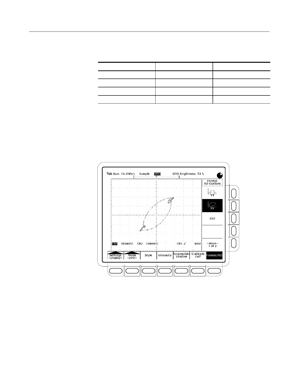
Figure 3–31: DPO XY Display

 Loading...