~-------
~
945423-9701
Bit Number
7
16
,
17
16
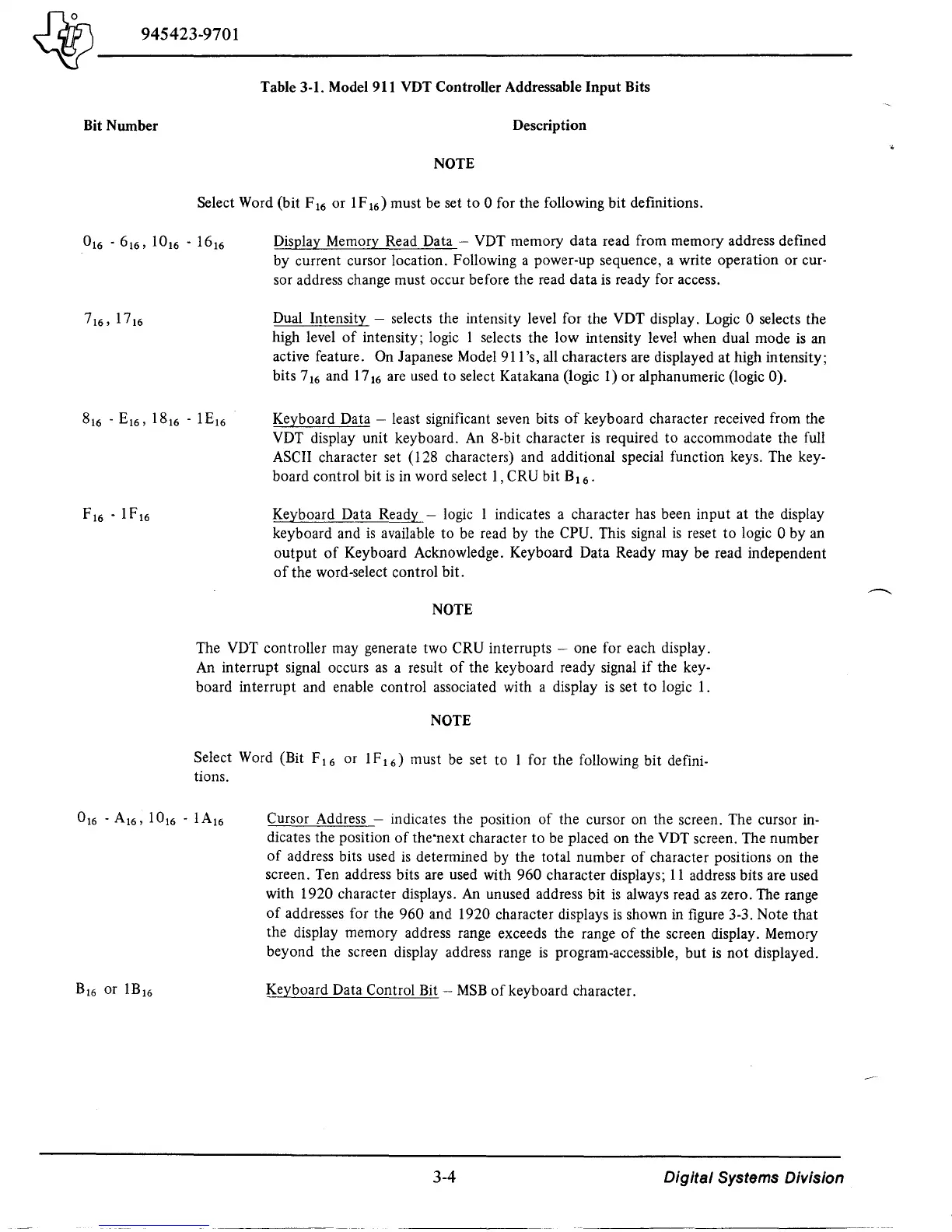
Table 3-1. Model 911 VDT Controller Addressable
Input
Bits
Description
NOTE
Select Word (bit F 16 or 1 F
16)
must be set
to
0 for the following bit definitions.
Display Memory Read Data
-
VDT
memory data read from memory address defined
by current cursor location. Following a power-up sequence, a write operation or
cur-
sor address change must occur before the read data
is
ready for access.
Dual Intensity
- selects the intensity level for the VDT display. Logic 0 selects the
high level
of
intensity; logic 1 selects the low intensity level when dual mode
is
an
active feature.
On
Japanese Model 911 's, all characters are displayed at high intensity;
bits 7
16
and 17
16
are used to select Katakana (logic
1)
or alphanumeric (logic 0).
Keyboard Data - least significant seven bits
of
keyboard character received from the
VDT display unit keyboard.
An
8-bit character
is
required
to
accommodate the full
ASCII character set (128 characters) and additional special function keys. The key-
board control bit
is
in
word select 1, CRU bit B
16
.
Keyboard Data Ready - logic 1 indicates a character has been input at the display
keyboard and
is
available to be read by the CPU. This signal
is
reset
to
logic 0 by an
output
of
Keyboard Acknowledge. Keyboard Data Ready may be read independent
of
the word-select control bit.
NOTE
The VDT controller may generate two CRU interrupts - one for each display.
An interrupt
Signal
occurs
as
a result
of
the keyboard ready signal
if
the key-
board interrupt and enable control associated with a display
is
set
to
logic 1.
NOTE
Select Word (Bit F
16
or 1F
16
) must be set to 1 for the following bit defini-
tions.
Cursor Address - indicates the position
of
the cursor on the screen. The cursor in-
dicates the position
of
the-next character to
be
placed on the VDT screen. The number
of
address bits used
is
determined
by
the total number
of
character positions on the
screen. Ten address bits are used with 960 character displays;
11
address bits are used
with 1920 character displays. An unused address bit
is
always read
as
zero. The range
of
addresses for the 960 and 1920 character displays
is
shown in figure 3-3. Note that
the display memory address range exceeds the range
of
the screen display. Memory
beyond the screen display address range
is
program-accessible, but
is
not
displayed.
Keyboard Data Control Bit -
MSB
of
keyboard character.
3-4
Digital Systems Division

 Loading...
