J175\
______
_
~
945423-9701
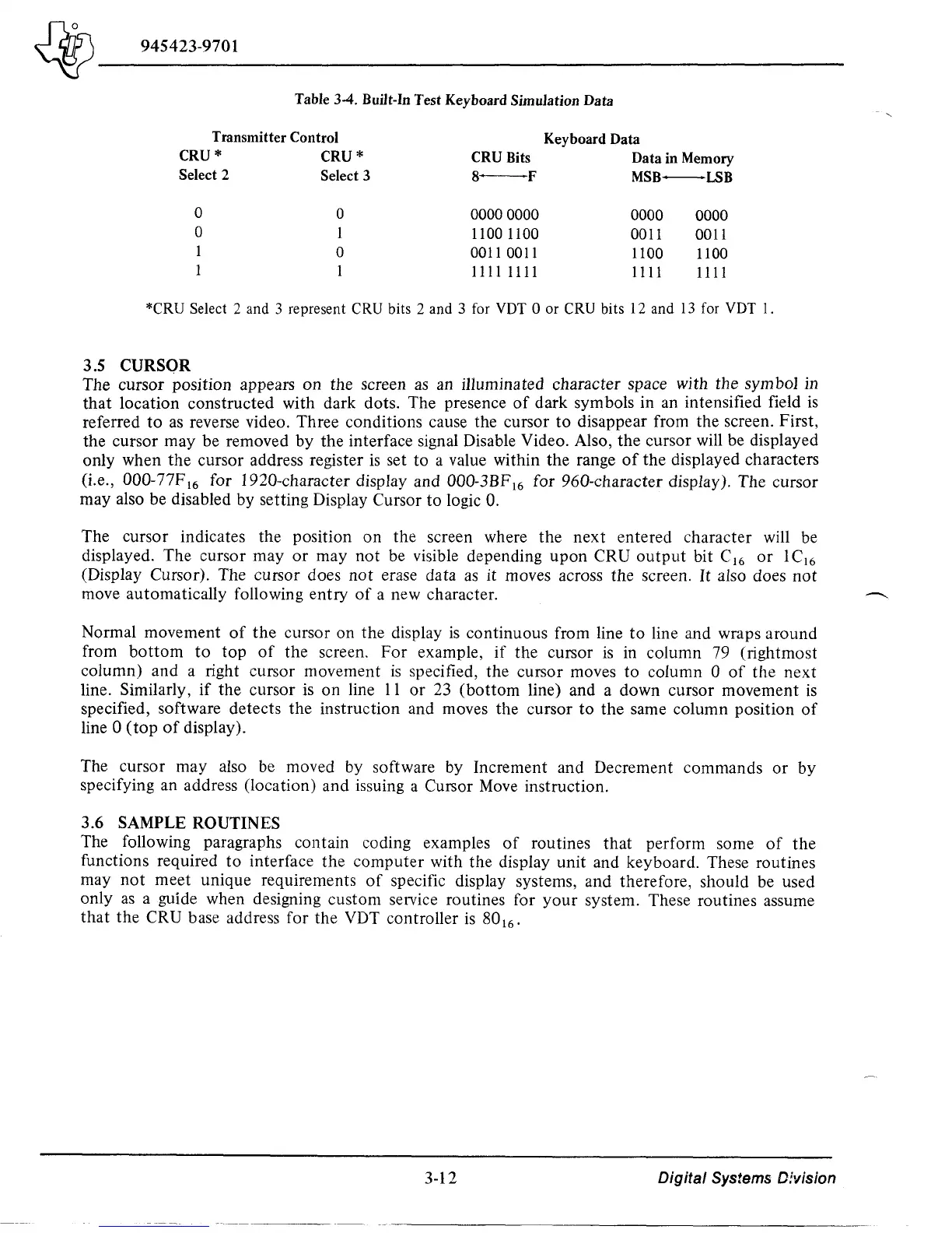
Table
34.
Built-In Test Keyboard Simulation Data
Transmitter
Control
Keyboard Data
CRU*
CRU*
CRU Bits
Data in Memory
Select 2
Select 3
8-F
MSB-LSB
0
0
00000000
0000
0000
0
1
1100 1lO0
0011 0011
0
0011 0011
1100
1lO0
1111 1111
1111
1111
*CRU Select 2 and 3 represent CRU bits 2 and 3 for vor 0 or CRU bits 12 and
13
for vor
1.
3.5 CURSOR
The cursor position appears
on
the screen
as
an illuminated character space with the
symbol
in
that
location constructed with dark dots. The presence
of
dark symbols in an intensified field
is
referred
to
as
reverse video. Three conditions cause the cursor
to
disappear from the screen. First,
the cursor may be removed by the interface signal Disable Video. Also, the cursor will be displayed
only when
the
cursor address register
is
set to a value within the range
of
the displayed characters
(i.e.,
000-77F 16 for 1920-character display and 000-3BF 16 for 960-character display). The cursor
may also be disabled by setting Display Cursor to logic
O.
The cursor indicates the position
on
the screen where the next entered character will be
displayed. The cursor
mayor
may
not
be visible depending
upon
CRU
output
bit C
16
or
lC
16
(Display Cursor). The cursor does
not
erase data
as
it moves across the screen.
It
also does
not
move automatically following entry
of
a new character.
Normal movement
of
the
cursor on
the
display
is
continuous from line
to
line and wraps around
from
bottom
to
top
of
the screen,
For
example,
if
the cursor
is
in column 79 (rightmost
column) and a right cursor movement
is
specified, the cursor moves to column 0
of
the next
line.
Similarly,
if
the cursor
is
on
line
11
or
23
(bottom
line) and a down cursor movement
is
specified, software detects the instruction and moves the cursor
to
the
same column position
of
line 0
(top
of
display).
The cursor may also be moved by software by Increment and Decrement commands
or
by
specifying an address (location) and issuing a Cursor
Move
instruction.
3.6 SAMPLE ROUTINES
The following paragraphs contain coding examples
of
routines that perform some
of
the
functions required
to
interface
the
computer
with the display unit and keyboard. These routines
may
not
meet
unique requirements
of
specific display systems, and therefore, should be used
only
as
a guide when designing custom service routines for
your
system. These routines assume
that
the CRU base address for the VDT controller
is
80
16
,
3-12
Digital
Systems D!vision

 Loading...
