Jd75\
______
_
~
945423-9701
Bit Number
o
Table 3-1. Model 911 VDT Controller Addressable
Input
Bits (Continued)
Description
Terminal Ready - normally indicates the status
of
the associated terminal. A logic 0
indicates the terminal
is
connected and available. A logic 1 indicates the terminal
is
turned
off
or disconnected. Also, when self-test mode
is
selected, terminal ready
is
set
to
logic 1.
Previous State Flag or Self-Test Signal - indicates the state
of
the word-select logic
before the last transfer
to
word
1.
Logic 0 indicates word 0
was
selected, and logic 1
indicates word 1
was
selected.
If
self-test mode
is
selected, this signal provides one
of
four test inputs.
The previous state
flag
permits interrupt-driven software
to
determine the controller
state prior
to
a keyboard interrupt. This permits the controller
to
process the interrupt
and restore previous conditions.
When test mode
is
selected, this bit has another function. In test mode the signal read
is
determined by two display memory write data bits: CRU output bits 0 and 1
of
word
O-VDT
0 and CRU outputs 10 and
11
of
word
O-VDT
1.
The signals read during
test mode are video, audio "beep", horizontal sync, and vertical sync. The signals and
their characteristics are summarized
in
table 3-2.
Keyboard Parity Error
- a logic 1 on this input indicates that a parity error occurred
on the previous keyboard data transmission. The error indication
is
reset by the output
signal, keyboard acknowledge. A logic 0 indicates the transmission had valid parity.
Keyboard Data Ready - Logic 1 indicates a character has been input at the display
keyboard and
is
available
to
be read by the CPU. This signal
is
reset
to
logic 0 by an
output
of
keyboard acknowledge.
NOTE
The VDT controller may generate two CRU interrupts.
An
interrupt signal
occurs
as
a result
of
the keyboard data ready signal from VDT 0 or VDT 1
if
the
respective keyboard interrupt enable control signal
is
set to logic 1.
2 _ -
__
-
____
4F
o
2 - - - - - - - - -
4F
50
- - - - - - - - - - - - -
9F
50
- - - - - - - - - - - - - -
9F
730
77F
370
3BF
I
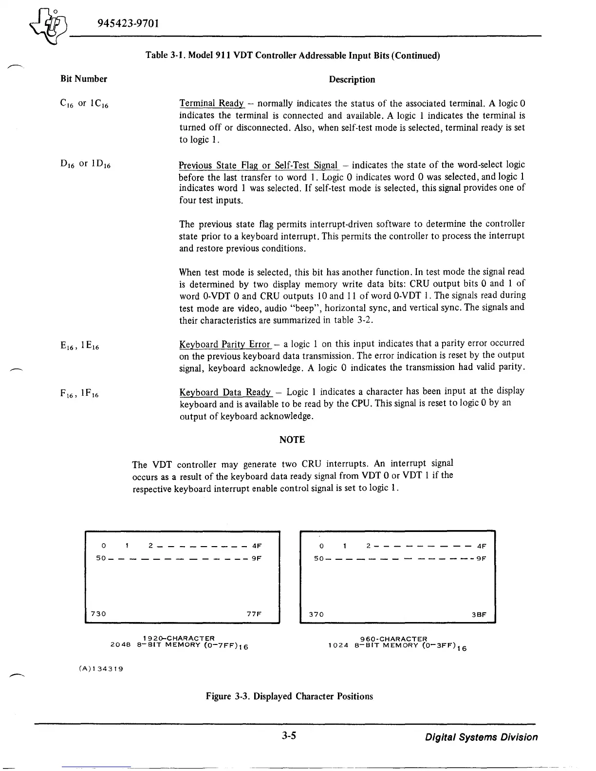
92G-CHARACTER
960-CHARACTER
2048
8-BIT
MEMORY
(0-7FF)16
1024
8-BIT
MEMORY
(0-3FF)
16
(A)134319
Figure 3-3. Displayed Character Positions
3-5
Digital Systems Division

 Loading...
