~~------------------
~
945423-9701
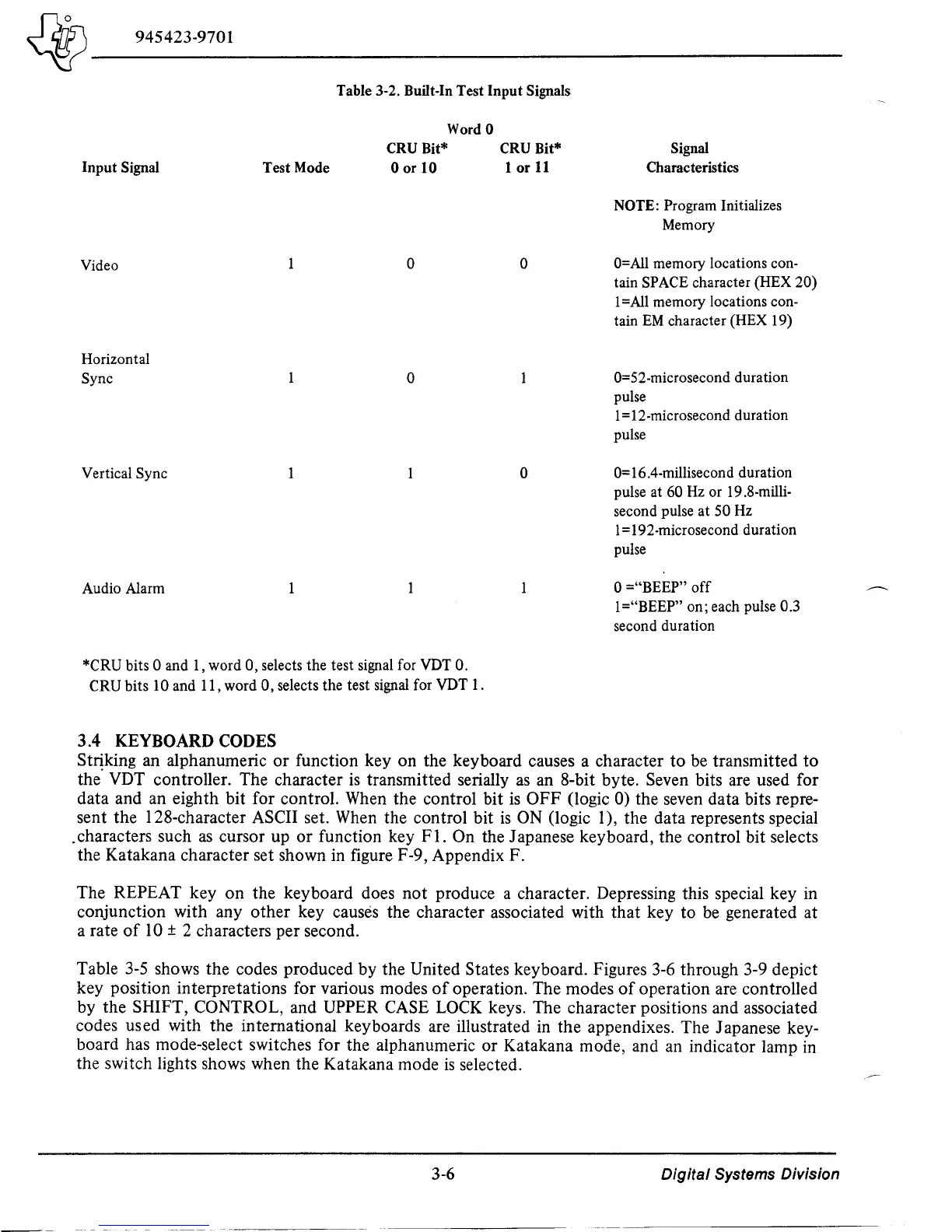
Table 3-2. Built-In Test Input Signals
Input Signal
Video
Horizontal
Sync
Vertical Sync
Audio Alarm
Test Mode
Word
0
CRU Bit*
Oorto
o
o
*CRU bits 0 and 1, word 0, selects the test signal for VDT
O.
CRU bits 10 and 11, word
0,
selects the test signal for VDT 1.
3.4 KEYBOARD CODES
CRU Bit*
lor
11
o
o
Signal
Characteristics
NOTE: Program Initializes
Memory
O=AlI
memory locations con-
tain SPACE character (HEX
20)
I=AlI memory locations con-
tain
EM
character (HEX 19)
0=52·microsecond duration
pulse
1=12·microsecond duration
pulse
0=16.4-millisecond duration
pulse at
60
Hz
or 19.8·milli-
second pulse at 50 Hz
1 =192-microsecond duration
pulse
o ="BEEP"
off
1 ="BEEP" on; each pulse 0.3
second duration
Striking an alphanumeric
or
function key on the keyboard causes a character
to
be transmitted
to
the' VDT controller. The character
is
transmitted serially
as
an 8-bit byte. Seven bits are used for
data and an eighth bit for control. When the control bit
is
OFF (logic
0)
the seven data bits repre-
sent the I 28-character ASCII set. When the control bit
is
ON
(logic I), the data represents special
.characters such
as
cursor up
or
function key
Fl.
On the Japanese keyboard, the control bit selects
the Katakana character set shown in figure F-9, Appendix F.
The REPEAT key on the keyboard does not produce a character. Depressing this special key in
conjunction with any other key causes the character associated with that key to be generated at
a rate
of
10 ± 2 characters per second.
Table
3-5
shows the codes produced by the United States keyboard. Figures 3-6 through 3-9 depict
key position interpretations for various modes
of
operation. The modes
of
operation are controlled
by the SHIFT,
CONTROL, and UPPER CASE
LOCK
keys. The character positions and associated
codes used with the international keyboards are illustrated
in
the appendixes. The Japanese key-
board has mode-select switches for the alphanumeric
or
Katakana mode, and an indicator lamp in
the switch lights shows when the Katakana mode
is
selected.
3-6
Digital Systems Division

 Loading...
