Jd75\
______
_
~
945423-9701
Keyboard
interpretations
for
the
four United States modes are shown in figures 3-6 through 3-9.
(Refer
to
the appendixes for
the
European and Japanese
keyboard
mode interpretations.)
The
related
input/output
(I/O)
software examines the code
to
determine
the
function. The repeat
feature permits
the
operator
to
hold down the REPEAT key and
then
press any
other
key
to
gen-
erate
the
accompanying character
(or
function) at a rate
of
10
± 2 characters per second.
4.3
DISPLAY UNIT CONTROLS AND INDICATORS
The display unit has controls and indicators
in
two positions
on
the display housing:
the
side
and rear
of
the
cabinet. The following paragraphs describe
the
functions
of
each
of
these
controls
and
indicators.
4.3.1
CONTROL
PANEL.
Three
controls
mounted
on the right side
of
the VDT
monitor
housing
comprise
the
control
panel. Figure 4-2 shows
the
controls.
The
ON/OFF
switch
is
a rocker switch
that
controls ac power
to
the
terminal.
The brightness and volume controls are rotary controls
that
allow the
operator
to vary
the
brightness
of
characters
on
the display and the loudness
of
the
audio alarm, respectively.
4.3.2
DATA INDICATORS. A row
of
10 light-emitting diode (LED) indicators are located in
the
center
of
the
rear panel
of
the
display unit housing
as
shown in figure 4-3. Figure 4-4 depicts
a closer view
of
the
indicators.
When lighted,
the
rightmost indicator (S) indicates
that
the
video sync pulse
is
being received
from
the
VDT controller. This indicator should always be lighted
if
computer
interface cables are
properly installed,
computer
and VDT power
is
on, and the VDT controller
is
inserted
into
the
computer
chassis and working properly.
When lighted
the
parity indicator (P) indicates
that
the parity bit sent
to
the VDT controller
with
the
last character bits was correct. This indicator should always be on
if
the system
is
connected properly,
power
is
on,
and
the
display unit
is
transmitting data properly
to
the VDT
con troller.
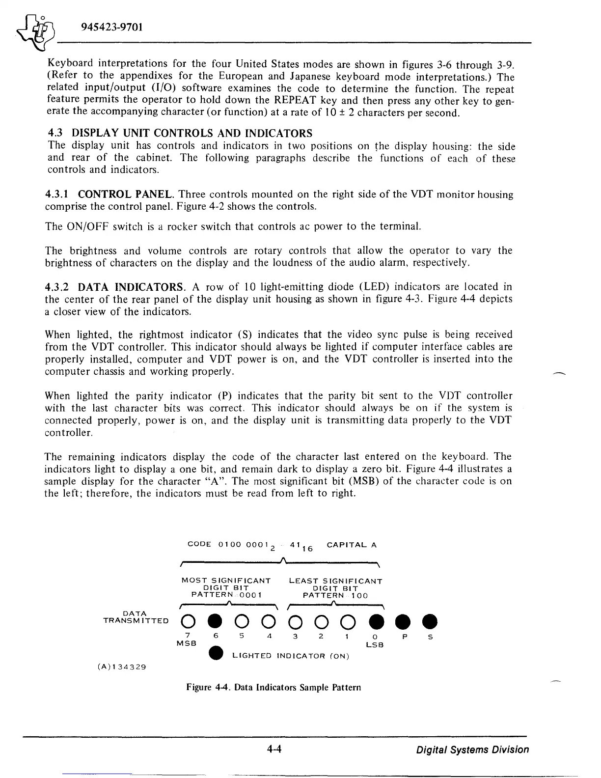
The remaining indicators display the code
of
the character last entered
on
the keyboard. The
indicators light
to
display a one bit, and remain dark to display a zero bit. Figure 4-4 illustrates a
sample display for
the
character
"A".
The most significant bit (MSB)
of
the
character code
is
on
the left; therefore,
the
indicators must be read from left
to
right.
CODE
0100
0001
2
41
16
CAPITAL
A
~
____________
-JA~
____________
~
MOST
SIGNIFICANT
DIGIT
BIT
PATTERN
0001
~
__
--,I\Ioo-
____
"""I
LEAST
SIGNIFICANT
DIGIT
BIT
PATTERN
100
,~
____
--.JI\~
___
"""I
DATA
TRANSMITTED
0 • 0 0 0 0 0 e e e
(A)134329
7
MSB
6 5
4
3
2
•
LIGHTED
INDICATOR
(ON)
Figure 4-4. Data Indicators Sample Pattern
4-4
a
LSB
P
S
Digital
Systems Division

 Loading...
