Voltage Reference
www.ti.com
10
SBAU090E–November 2003–Revised November 2018
Submit Documentation Feedback
Copyright © 2003–2018, Texas Instruments Incorporated
ADS1256EVM and ADS1256EVM-PDK
4.1.6 J10 Pins 5-6: AGND Select
Shorting this jumper connects the ADS1256EVM ground net to AGND. For normal operation, J4.1-2, J4.3-
4, and J4.9-10 must be connected (either directly or through an ammeter); either J4.5-6 or J4.7-8 must be
connected, and either (or both) of J4.11-12 and J4.13-14 must be connected, as well. Otherwise, the
board will not function. Refer to Table 5 for details.
Table 5. J4, J9, and J10 Configuration: Power Options
Row Name Function
1-2 ADC AVDD AVDD supply current measurement point for the
ADC. Must be connected for operation.
3-4 ADC AVSS AVSS supply current measurement point for the
ADC. Must be connected for operation.
5-6 1.8V select When shorted, DVDD is sourced from the 1.8V
power-supply input pin. Should not be connected at
the same time as 7-8.
7-8 3.3V select When shorted, DVDD is sourced from the 3.3V
power-supply input pin. Should not be connected at
the same time as 5-6.
9-10 ADCDVDD DVDD supply current measurement point for the
ADC. Must be connected for operation.
11-12 DGND Connects DGND to board ground.
13-14 AGND Connects AGND to board ground.
5 Voltage Reference
The ADS1256EVM has several reference options that can be selected by switch S3. First, there are
connections to apply an external reference voltage to the analog input header. The user can apply a
reference voltage to J1.18 and J1.20 in order to set the reference.
The ADS1256 also has a buffered REF5025 on board. This 2.5V reference can also be selected by switch
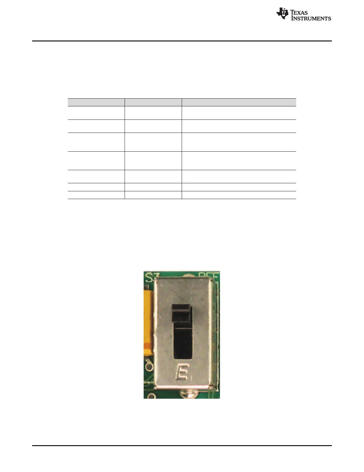
S3. VRN to VRP can be set from AGND to 2.5V or from 2.5V to AVDD. Figure 4 illustrates how switch S3
appears on the board. A description of switch S3 is provided in Table 6.
Figure 4. Switch S3

 Loading...


