ADS1256EVM-PDK Kit Operation
www.ti.com
18
SBAU090E–November 2003–Revised November 2018
Submit Documentation Feedback
Copyright © 2003–2018, Texas Instruments Incorporated
ADS1256EVM and ADS1256EVM-PDK
The software should now be installed, but the USB drivers may not yet have been loaded by the PC
operating system. This step completes when the ADCPro software is executed; see Section 8.4, Running
the Software and Completing Driver Installation.
8.2 Setting Up the ADS1256EVM-PDK
The ADS1256EVM-PDK contains both the ADS1256EVM and the MMB0 motherboard; however, these
devices are shipped unconnected. Follow these steps to set up the ADS1256EVM-PDK:
Step 1. Unpack the ADS1256EVM-PDK kit.
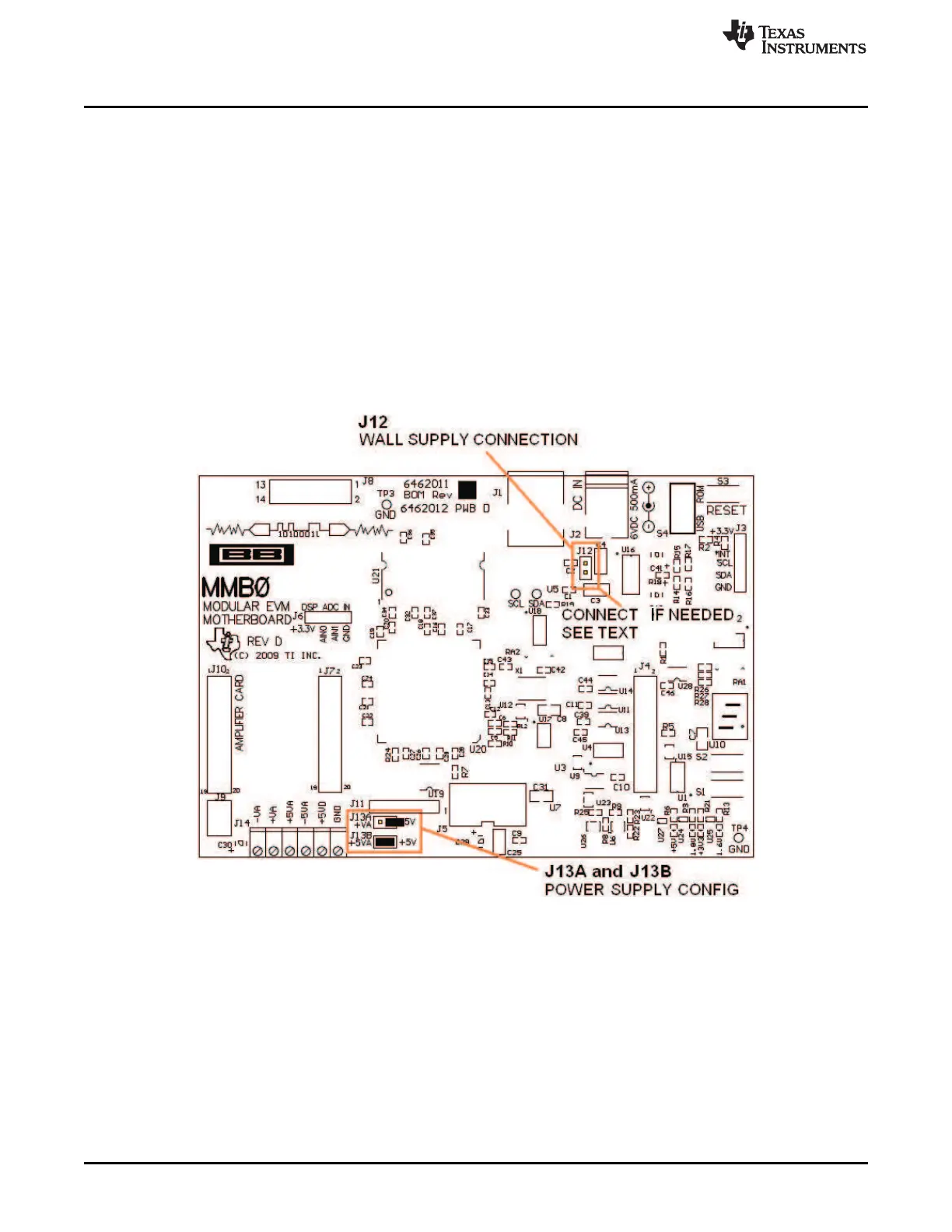
Step 2. Set the jumpers and switches on the MMB0 as shown in Figure 12.
• Connect +5V and +5VA on jumper block J13 (if +5V is supplied from J14 +5VA).
• Leave +5V and +VA disconnected on jumper block J13.
• If the PDK will be powered from an ac adapter, and used in unipolar mode, connect J12.
If the PDK will be powered through the terminal block or will be used in bipolar mode,
disconnect J12. (See Section 8.3 for details on connecting the power supply.)
Figure 12. MMB0 Initial Configuration

 Loading...


