EVM Operation
www.ti.com
12
SBAU090E–November 2003–Revised November 2018
Submit Documentation Feedback
Copyright © 2003–2018, Texas Instruments Incorporated
ADS1256EVM and ADS1256EVM-PDK
7 EVM Operation
This section provides information on the analog input, digital control, and general operating conditions of
the ADS1256EVM.
7.1 Analog Input
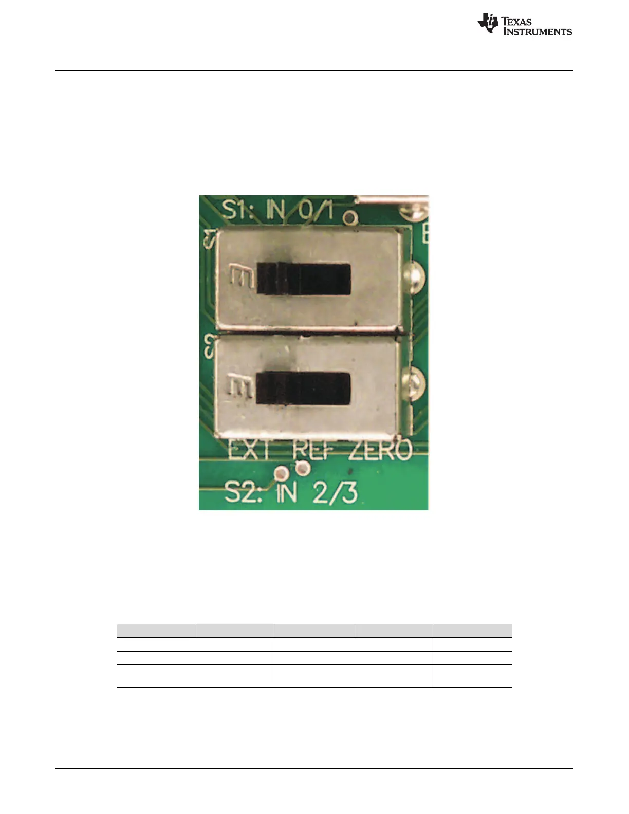
The analog input sources can be applied directly to J1 (top or bottom side). Additionally, switches S1 and
S2 must be set to route the input signals from J1. Otherwise, the inputs are used to measure the
reference or inputs shorted to the reference. Switches S1 and S2 are shown in Figure 6.
Figure 6. Switches S1 and S2
7.1.1 S1: AIN0-1 Input Select
These switches control which lines are routed to the ADS1256 AIN0-AIN1 inputs. Table 8 shows the
positions of these switches.
Table 8. AIN0-1 Input Select Switch (S1)
Board Marking Switch Position Input Source AIN0 Connection AIN1 Connection
EXT Left External J1.2 J1.1
REF Middle Reference voltage +2.5V AGND
ZERO Right Zero (shorted to
reference)
+2.5V +2.5V

 Loading...


