O
PERATING
M
ANUAL
DAF380
M
OUNTING THE
M
ACHINE
ThyssenKrupp Aufzugswerke GmbH
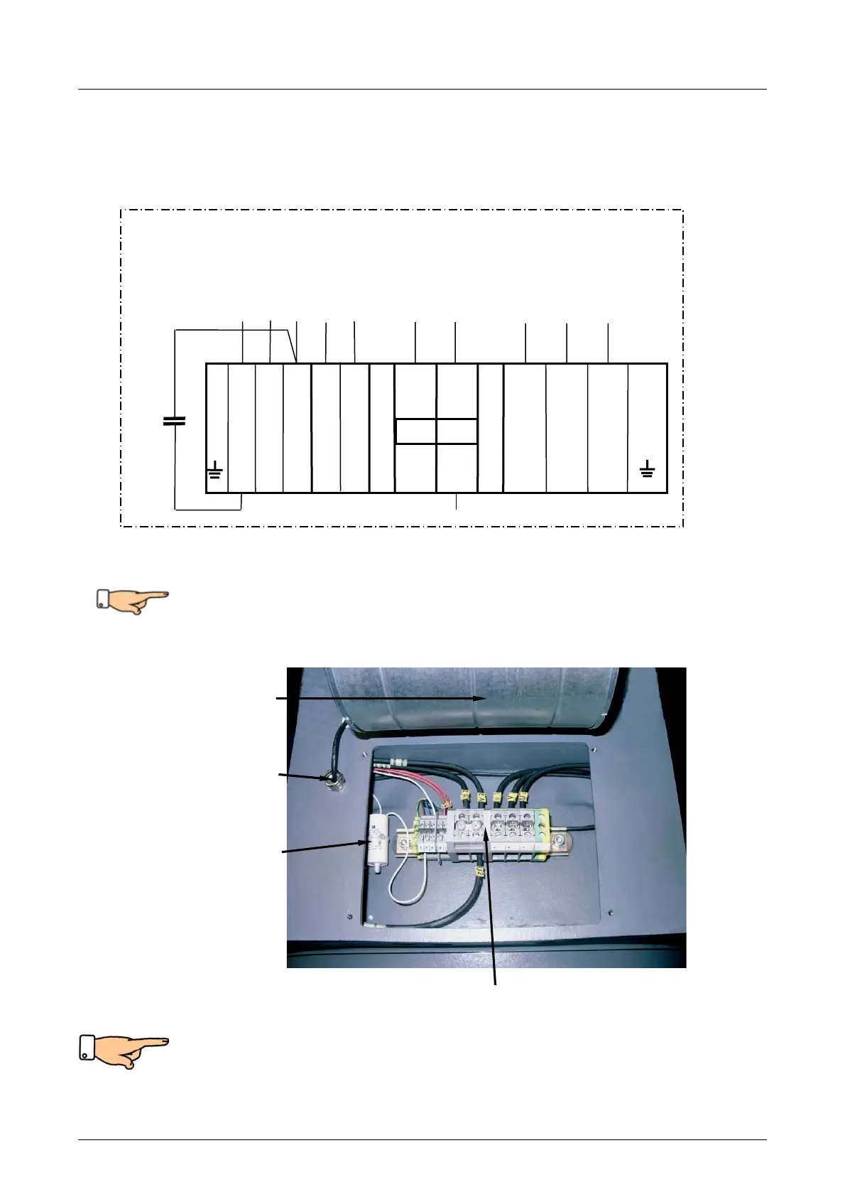
5.3 Terminal connecting plans
Motor connection terminal plan:
Do not apply a voltage greater than 2.5 V at the terminals of the
posistor. Adhere to the internal resistance of the measurement devices!
The terminal diagram is printed on the inside of the cover.
Note: Observe direction of rotation.
The ventilation must be connected in such a way that the air flow is drawn in
and blown through the motor.
See direction of arrow on the air inlet side on the ventilation.
Fig. 5.4
Fan
Cable feed through
for fan
Capacitor
Terminals for motor, temperature monitoring and fan
Fig. 5.3
13 14 15 10 11
1
2
3
2µF
450
W2
entilation
Neutral
Posistor
 Loading...