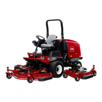
Figure65
1.Hydraulicmotor2.Mountingbolts
5.Removetheoldbeltfromaroundthespindlepulleys
andidlerpulley.
6.Routethenewbeltaroundthespindlepulleysand
idlerpulleyassembly.
7.Positionthehydraulicmotoronthecuttingunitafter
routingthebeltaroundthepulleys.Mountthemotor
tothecuttingunitwiththeboltspreviouslyremoved.
Note:Makesurethebeltispositionedonthespring
sideofthebeltguide(Figure64).
8.Reconnecttheextensionspring(Figure64)tothe
eyeboltandtensionthebeltasfollows:
•Whenproperlytensioned,theextension
spring(hooktohook)measurementshouldbe
approximately3.50±.25inch(inside).
•Oncethecorrectspringtensionisattained,
adjustthestopbolt(carriagebolt)untilthereis
approximately.125+.060/-.000inchclearance
betweentheheadoftheboltandtheidlerarm.
ControlsSystem
Maintenance
AdjustingtheThrottleCable
ServiceInterval:Aftertherst50hours—Checkthe
enginespeed(atidleandfullthrottle).
Every400hours—Checktheengine
speed(atidleandfullthrottle).
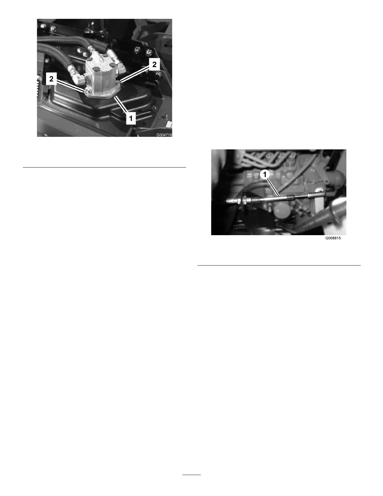
Adjustthethrottlecable(Figure66)sothatthegovernor
leverontheenginecontactsthelowandhighspeedset
boltsbeforethethrottlelevercontactstheslotinthe
controlpanel.
Figure66
1.Throttlecable
AdjustingtheTractionPedal
Linkage
Withthetractionpedalinthemowposition(lowspeed)
itshouldreachfullstrokeatthesametimeitmakes
contactwiththestop.Ifitdoesnot,performthe
followingprocedure:
1.Parkthemachineonalevelsurface,stoptheengine,
andlowerthecuttingunitstotheoor.Removethe
ignitionkey.
2.Checkthetractionpedalstopadjustment.The
distancefromthetopofthestandtothetopof
thestopmustbe1-1/2inch(38mm)(Figure67).
Loosenthenutsandadjust,asrequired.
47

 Loading...