Workman GTX GasolinePage 5 − 22Electrical System
8. If battery voltage in step 5 above did not increase to
14.5 VDC and starter/generator tested correctly in step
7 above, test voltage regulator:
A. Set multimeter to VDC. Connect red (+) multime-
ter probe to the starter/generator terminal DF (Fig.
27). Connect black (−) multimeter probe to a known
good ground.
B. Start and run the engine at mid−range RPM.
C. The measured voltage should be approximately
2 VDC when the battery is charging and from 6 to 8
VDC when the battery is fully charged. This voltage
may rise to 14 VDC when the accelerator pedal is re-
leased and the engine is coasting to a stop.
D. If measured voltage is incorrect, stop engine and
replace voltage regulator. Retest charging circuit af-
ter replacing voltage regulator (Step 5 above).
9. When testing is complete, stop engine and remove
multimeter leads.
10.Install seat base assembly to vehicle.
11. Install rear frame panel cover to vehicle. Lower and
secure the cargo bed.
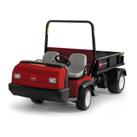
1. Starter/generator
2. Voltage regulator
3. Start/run solenoid
Figure 27
3
2
1
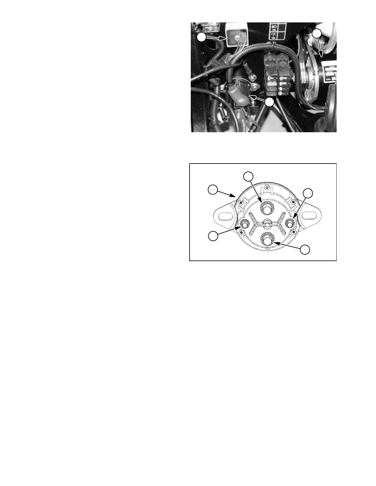
Figure 28
1. Start/run solenoid
2. Harness wire (black)
3. Starter/gen cable (to F2) and red wire (to volt regulator)
4. Harness wire (blue)
5. Positive battery cable and red wire (to fuse blocks)
5
2
3
4
1

 Loading...